uiThreshErode
Below is a demonstration of the features of the uiThreshErode function
Contents
clear; close all; clc;
Plot settings
cMap=gray(250);
faceAlpha1=1;
edgeColor1='none';
Example image of head surrounded by background
% Get a 3D image
load mri;
M=double(squeeze(D)); %example image data set
v=2./[1,1,.4]; %example voxel size

%Normalising
M=M-min(M(:));
M=M./max(M(:));

%Adding some noise
M=M+0.25.*rand(size(M));
Thresholding and erosion (and regrowing) based background removal
Start thresholding followed by dilation/erosion process
thresholdInitial=0.1; %with respect to normalised image
preBlurKernalSize=0; %with respect to normalised image
groupCropOption=0;
Uncomment to run code [L_BG]=uiThreshErode(M,thresholdInitial,preBlurKernalSize,groupCropOption);
Uncomment to run code
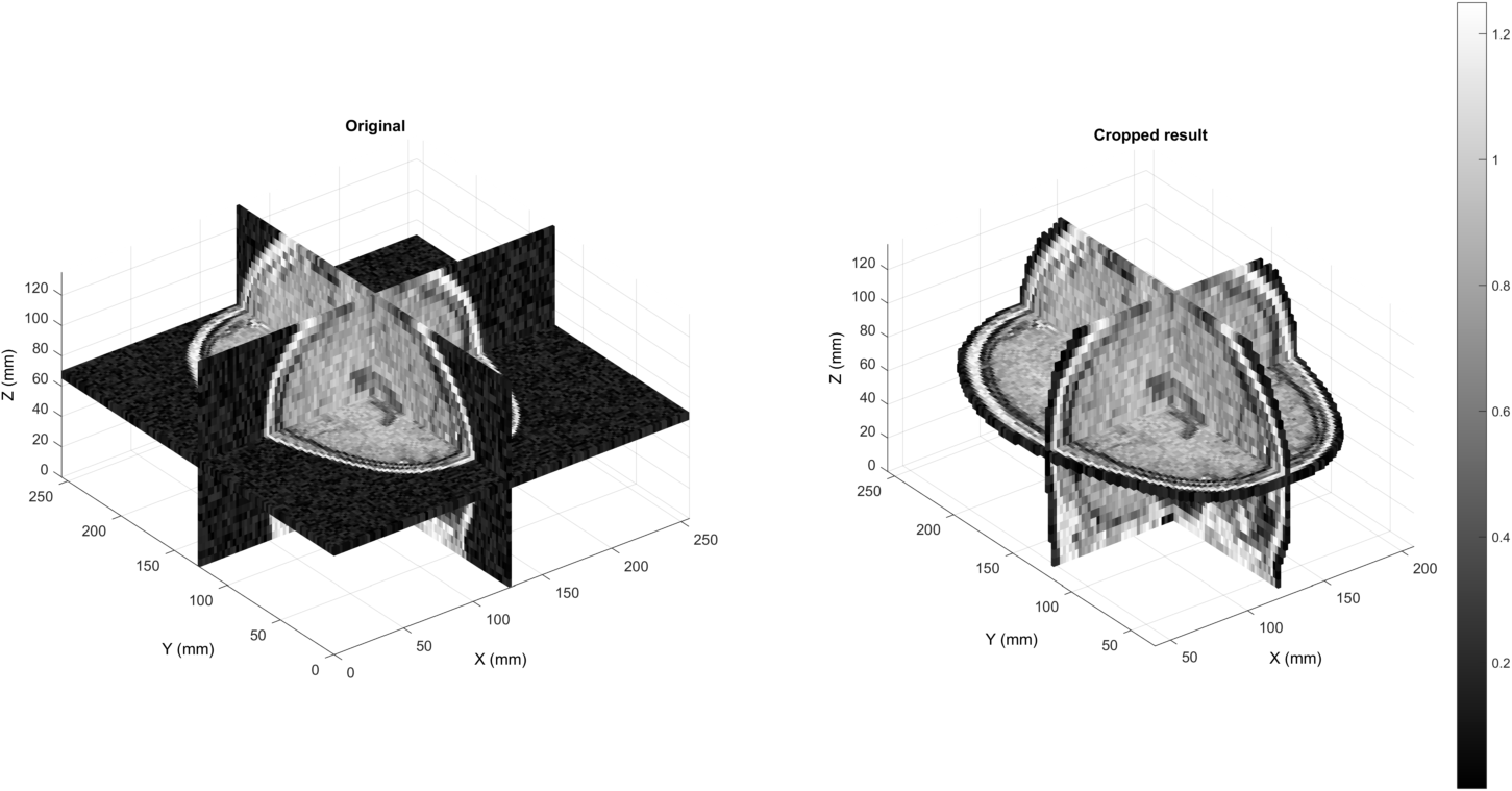
% % Plotting the cropped image
% logicVoxels=false(size(M));
% logicVoxels(round(size(M,1)/2),:,:)=1;
% logicVoxels(:,round(size(M,2)/2),:)=1;
% logicVoxels(:,:,round(size(M,3)/2))=1;
%
% logicVoxels1=logicVoxels;
% [F1,V1,C1]=ind2patch(logicVoxels1,M,'vb');
% [V1(:,1),V1(:,2),V1(:,3)]=im2cart(V1(:,2),V1(:,1),V1(:,3),v);
%
% logicVoxels2=logicVoxels & L_BG;
% [F2,V2,C2]=ind2patch(logicVoxels2,M,'vb');
% [V2(:,1),V2(:,2),V2(:,3)]=im2cart(V2(:,2),V2(:,1),V2(:,3),v);
%
% h1=cFigure;
%
% subplot(1,2,1);title('Original');
% xlabel('X (mm)');ylabel('Y (mm)'); zlabel('Z (mm)'); hold on;
% hp1= patch('Faces',F1,'Vertices',V1,'FaceColor','flat','CData',C1,'EdgeColor',edgeColor1,'FaceAlpha',faceAlpha1);
% axis equal; view(3); axis tight; axis vis3d; grid on;
%
% subplot(1,2,2);title('Cropped result');
% xlabel('X (mm)');ylabel('Y (mm)'); zlabel('Z (mm)'); hold on;
% hp1= patch('Faces',F2,'Vertices',V2,'FaceColor','flat','CData',C2,'EdgeColor',edgeColor1,'FaceAlpha',faceAlpha1);
% axis equal; view(3); axis tight; axis vis3d; grid on;
% colormap(cMap); colorbar;
% drawnow;
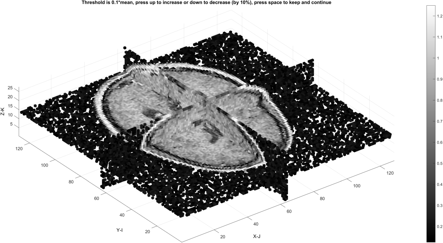
First the image data is visualized with an initial threshold applied:
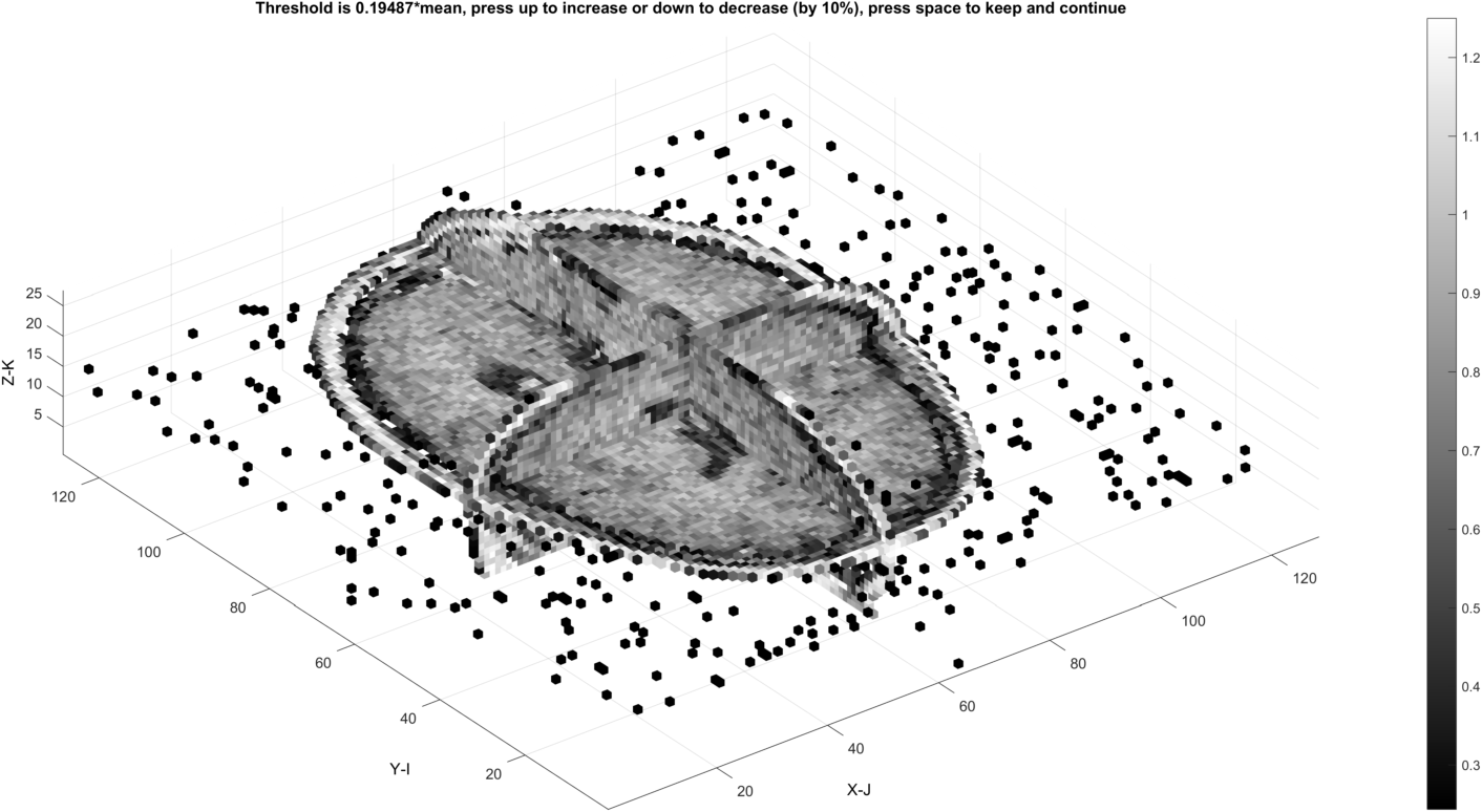
Increasing the threshold (up arrow key) removes more background voxels
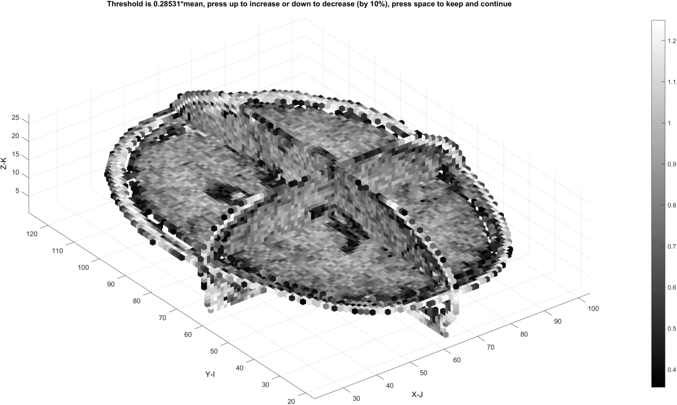
The threshold may also create undesired internal gaps at the level where all background is removed.
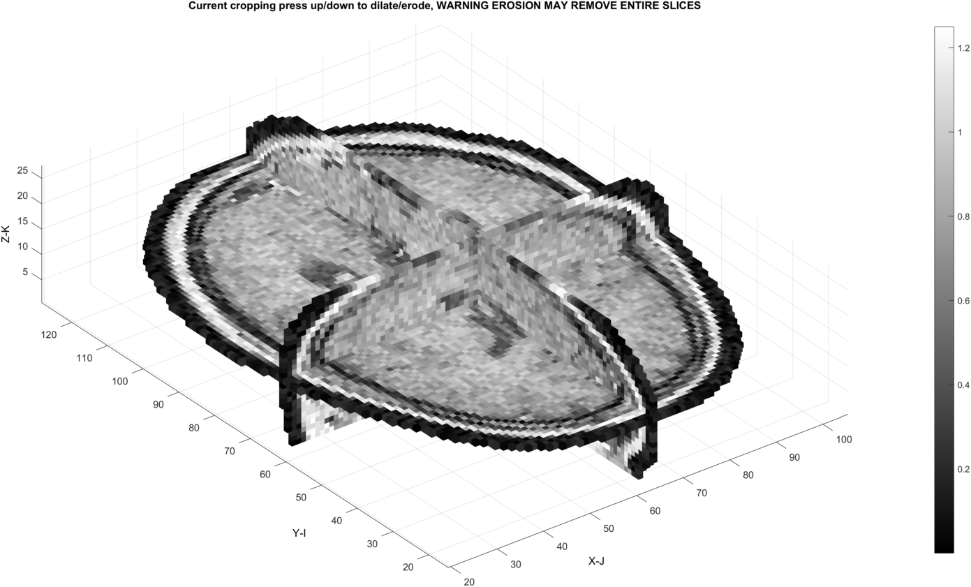
Dilations may fill in these gaps:
Comparing the final result (right) to the input (left):

GIBBON www.gibboncode.org
Kevin Mattheus Moerman, [email protected]
GIBBON footer text
License: https://github.com/gibbonCode/GIBBON/blob/master/LICENSE
GIBBON: The Geometry and Image-based Bioengineering add-On. A toolbox for image segmentation, image-based modeling, meshing, and finite element analysis.
Copyright (C) 2019 Kevin Mattheus Moerman
This program is free software: you can redistribute it and/or modify it under the terms of the GNU General Public License as published by the Free Software Foundation, either version 3 of the License, or (at your option) any later version.
This program is distributed in the hope that it will be useful, but WITHOUT ANY WARRANTY; without even the implied warranty of MERCHANTABILITY or FITNESS FOR A PARTICULAR PURPOSE. See the GNU General Public License for more details.
You should have received a copy of the GNU General Public License along with this program. If not, see http://www.gnu.org/licenses/.