DEMO_mesh_bifurcation_angle_control
This demo shows the use of the splitCurveSetMesh function to parameterise a bifurcation in terms of vessel directions and diameters.
Contents
clear; close all; clc;
PLOT SETTINGS
fontSize=15;
lineWidth=3;
markerSize1=25;
Control parameters
r1_inner=3;
r=(0.5*r1_inner^3)^(1/3);
r2_inner=r*0.9;
r3_inner=r*0.75;
pointSpacingMain=0.5;
V1_origin=[0 0 0]; %Origin of first circle
bifurcationAngleDeg2=35;
bifurcationAngleDeg3=-45;
bifurcationDistance2=4;
bifurcationDistance3=4;

height1=5;
height2=3;
height3=2;

nSmoothBifurcation=50; %Number of Laplacian/HC smoothing steps
splitMethod='ortho'; %'nearMid'; %Saddle placement
saddleArcHeightFactor=1; %1=saddle arcs upward to max height, 0 means saddle is in plane of first circle

nSmoothFinal=50; %Number of Laplacian/HC smoothing steps

wallThickness=0.5;
numElementsWall=2;
Derived metrics
nz=[0 0 1]; %Normal direction for z-axis
R2=euler2DCM([0 (bifurcationAngleDeg2/180)*pi 0]); %Rotation matrix for first direction
R3=euler2DCM([0 (bifurcationAngleDeg3/180)*pi 0]); %Rotation matrix for second direction

n2=nz*R2; %Direction vector for first branch
n3=nz*R3; %Direction vector for second branch

V2_origin=n2.*bifurcationDistance2; %Origin of second circle
V3_origin=n3.*bifurcationDistance3; %Origin of third circle

%Number of points to use allong circle 1
np=ceil((2*pi*r1_inner)./pointSpacingMain);
np=np+~iseven(np); %Forcing this even creates symmetric saddle position

%Number of steps from first circle to set of branch circles
numStepsBranch=ceil((bifurcationDistance2+bifurcationDistance3)/2./pointSpacingMain);
Create curves
Building outer radius here as thickening direciton is inwards.
% Circle 1
t=linspace(2*pi,0,np+1)'; t=t(1:end-1);
x=(r1_inner+wallThickness).*sin(t(:));
y=(r1_inner+wallThickness).*cos(t(:));
z=zeros(size(t));
V1=[x y z];
V1=V1+V1_origin;

% Circle 2
x=(r2_inner+wallThickness).*sin(t);
y=(r2_inner+wallThickness).*cos(t);
z=zeros(size(x));
V2=[x y z]*R2;
V2=V2+V2_origin+V1_origin;

% Circle 3
x=(r3_inner+wallThickness).*sin(t);
y=(r3_inner+wallThickness).*cos(t);
z=zeros(size(t));
V3=[x y z]*R3;
V3=V3+V3_origin+V1_origin;
Meshing bifurcation
V_cell={V1,V2,V3};
patchType='quad';
smoothPar.Method='HC';
smoothPar.n=nSmoothBifurcation;
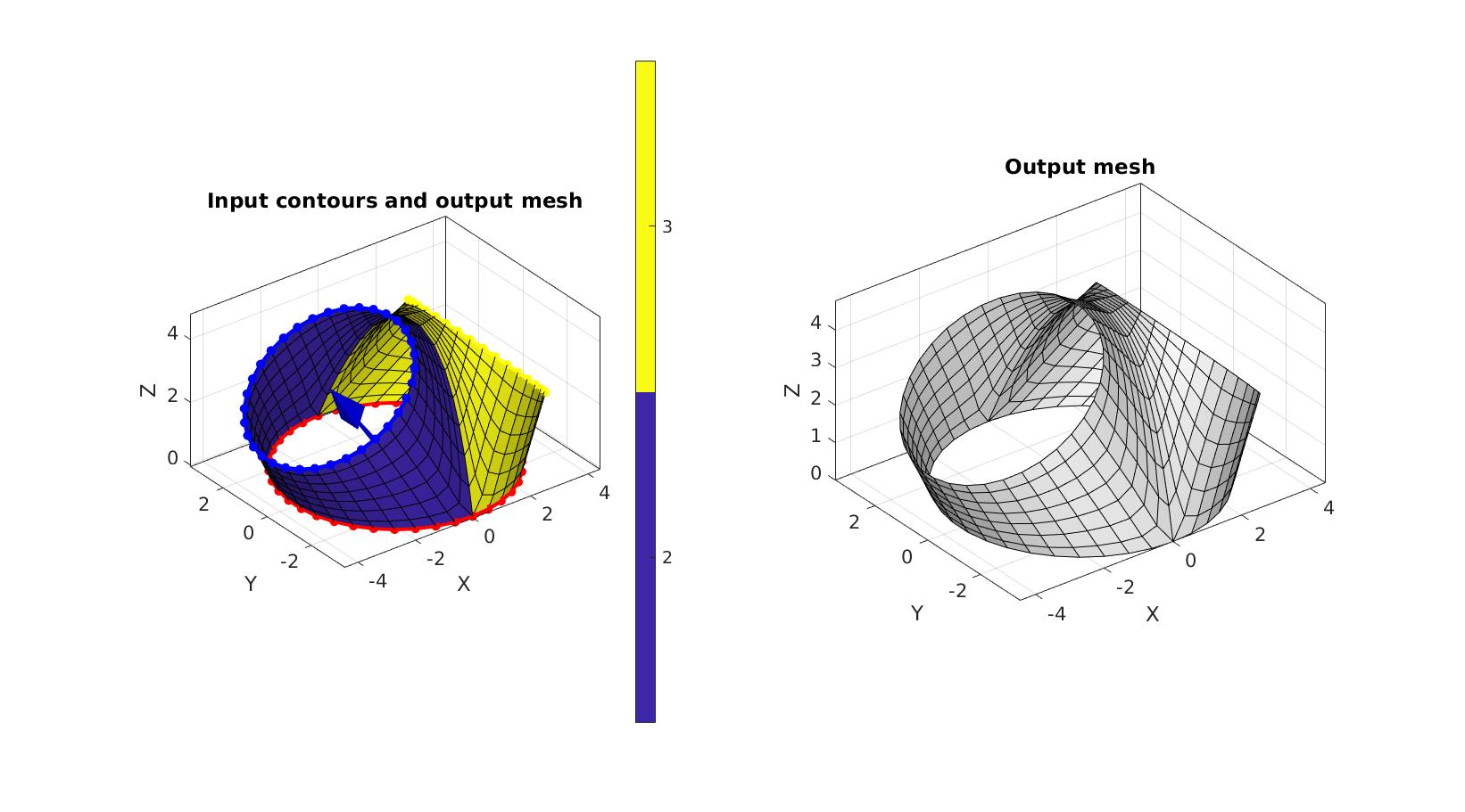
[Fb,Vb,curveIndices,Cb]=splitCurveSetMesh(V_cell,numStepsBranch,patchType,smoothPar,splitMethod,saddleArcHeightFactor);
Visualization
cFigure;
subplot(1,2,1); hold on;
title('Input contours and output mesh','FontSize',fontSize);
gpatch(Fb,Vb,Cb);
plotV(Vb(curveIndices{1},:),'r.-','MarkerSize',markerSize1,'LineWidth',lineWidth);
plotV(Vb(curveIndices{2},:),'b.-','MarkerSize',markerSize1,'LineWidth',lineWidth);
plotV(Vb(curveIndices{3},:),'y.-','MarkerSize',markerSize1,'LineWidth',lineWidth);
quiverVec(V1_origin,n2,bifurcationDistance2,'b')
quiverVec(V1_origin,n3,bifurcationDistance3,'y')
axisGeom(gca,fontSize);
colormap parula; icolorbar;
camlight headlight;

subplot(1,2,2); hold on;
title('Output mesh','FontSize',fontSize);
gpatch(Fb,Vb,'w','k');
axisGeom(gca,fontSize);
camlight headlight;

drawnow;
Extrude ends
cPar.numSteps=ceil(height1./pointSpacingMain);
cPar.depth=height1;
cPar.patchType='quad';
cPar.dir=1;
cPar.n=[0 0 -1];
cPar.closeLoopOpt=1;
[Fm,Vm]=polyExtrude(Vb(curveIndices{1},:),cPar);
Fm=fliplr(Fm);

pointSpacing2=mean(diff(pathLength(Vb(curveIndices{2},:))));
cPar.numSteps=ceil(height2./pointSpacing2);
cPar.depth=height2;
cPar.patchType='quad';
cPar.dir=1;
cPar.n=n2;
cPar.closeLoopOpt=1;
[Fb1,Vb1]=polyExtrude(Vb(curveIndices{2},:),cPar);
Fb1=fliplr(Fb1);

pointSpacing3=mean(diff(pathLength(Vb(curveIndices{3},:))));
cPar.numSteps=ceil(height3./pointSpacing3);
cPar.depth=height3;
cPar.patchType='quad';
cPar.dir=1;
cPar.n=n3;
cPar.closeLoopOpt=1;
[Fb2,Vb2]=polyExtrude(Vb(curveIndices{3},:),cPar);
Fb2=fliplr(Fb2);
Join and merg
[F,V,C]=joinElementSets({Fm,Fb,Fb1,Fb2},{Vm,Vb,Vb1,Vb2},{ones(size(Fm,1),1),Cb,2*ones(size(Fb1,1),1),3*ones(size(Fb2,1),1)});
[F,V]=mergeVertices(F,V);
Smoothen
smoothPar2.Method='HC';
smoothPar2.n=nSmoothFinal;
smoothPar2.RigidConstraints=unique(patchBoundary(F));
V=patchSmooth(F,V,[],smoothPar2);
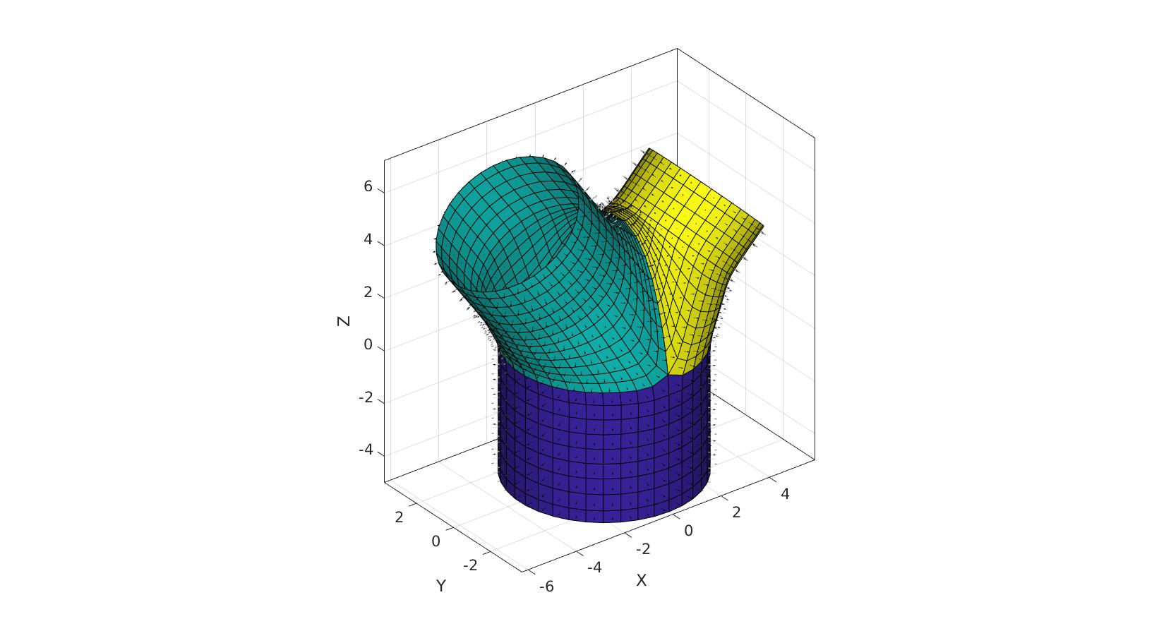
Visualization
cFigure; hold on;
gpatch(F,V,C,'k');
patchNormPlot(F,V);

% gpatch(Fb,Vb,'w','k');
% patchNormPlot(Fb,Vb);
% gpatch(Fm,Vm,'w','k');
% patchNormPlot(Fm,Vm);
% gpatch(Fb1,Vb1,'w','k');
% patchNormPlot(Fb1,Vb1);
% gpatch(Fb2,Vb2,'w','k');
% patchNormPlot(Fb2,Vb2);
axisGeom(gca,fontSize);
camlight headlight;

drawnow;
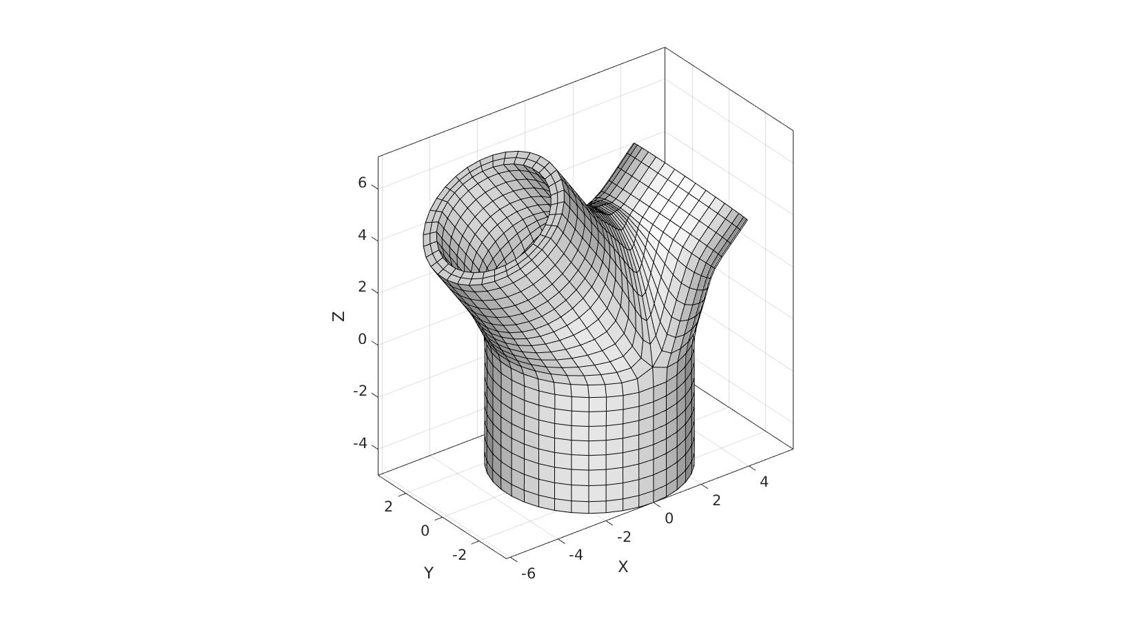
[E,V]=patchThick(F,V,-1,wallThickness,numElementsWall);

FE=element2patch(E);
Visualization
cFigure; hold on;
gpatch(FE,V,'w','k');
axisGeom(gca,fontSize);
camlight headlight;

drawnow;

GIBBON www.gibboncode.org
Kevin Mattheus Moerman, [email protected]
GIBBON footer text
License: https://github.com/gibbonCode/GIBBON/blob/master/LICENSE
GIBBON: The Geometry and Image-based Bioengineering add-On. A toolbox for image segmentation, image-based modeling, meshing, and finite element analysis.
Copyright (C) 2006-2021 Kevin Mattheus Moerman and the GIBBON contributors
This program is free software: you can redistribute it and/or modify it under the terms of the GNU General Public License as published by the Free Software Foundation, either version 3 of the License, or (at your option) any later version.
This program is distributed in the hope that it will be useful, but WITHOUT ANY WARRANTY; without even the implied warranty of MERCHANTABILITY or FITNESS FOR A PARTICULAR PURPOSE. See the GNU General Public License for more details.
You should have received a copy of the GNU General Public License along with this program. If not, see http://www.gnu.org/licenses/.