DEMO_heart_contours_hex_mesh_warping_01.m
Below is a demonstration for:
- Building a hexahedral mesh for a heart shape based on morphing of a template
- A template quad mesh is warped to match the shape of several curves
- The quads are next joined as hexahedral elements for the interior (fluid) domain
- The outer faces are next thickened to create a cardiac wall
Contents
- Keywords
- Plot settings
- Control parameters
- Building a quadrilateral circular template mesh
- Define target control points
- Visualize template mesh and control points
- Morph template quad mesh
- Build hexahedral elements of interior
- Bound wall mesh from by offsetting interior
- Join and merge wall and interior mesh
- Visualize final mesh
Keywords
- Warping
- hexahedral meshing
- heart, cardiac
- Cylindrical, circular
clear; close all; clc;
Plot settings
fontSize=15;
edgeWidth=2;
Control parameters
% discQuadMesh parameters
ne=6; %Elements in radius
f=0.5; %Fraction (with respect to outer radius) where central square appears

%Control point parameters
numLayers=18; %Number of control curve layers
heartHeight=65;

%Interpolation settings for warping
interpMethod='linear';
extrapMethod='linear';

%Thickening settings
layerThickness=4; %Wall thickness
numSteps=3; %Number of elements across wall
Building a quadrilateral circular template mesh
%Create the mesh
[F_template,V_template]=discQuadMesh(ne,1,f);
V_template(:,3)=0;
F_template=fliplr(F_template);
Eb=patchBoundary(F_template);
indB=edgeListToCurve(Eb);
indB=indB(1:end-1);
Smoothen mesh
cPar.n=50;
cPar.Method='LAP';
cPar.RigidConstraints=indB; %Hold on to boundary
[V_template]=patchSmooth(F_template,V_template,[],cPar);

%Define control points on template mesh
V_control_template=V_template(indB,:);
Define target control points
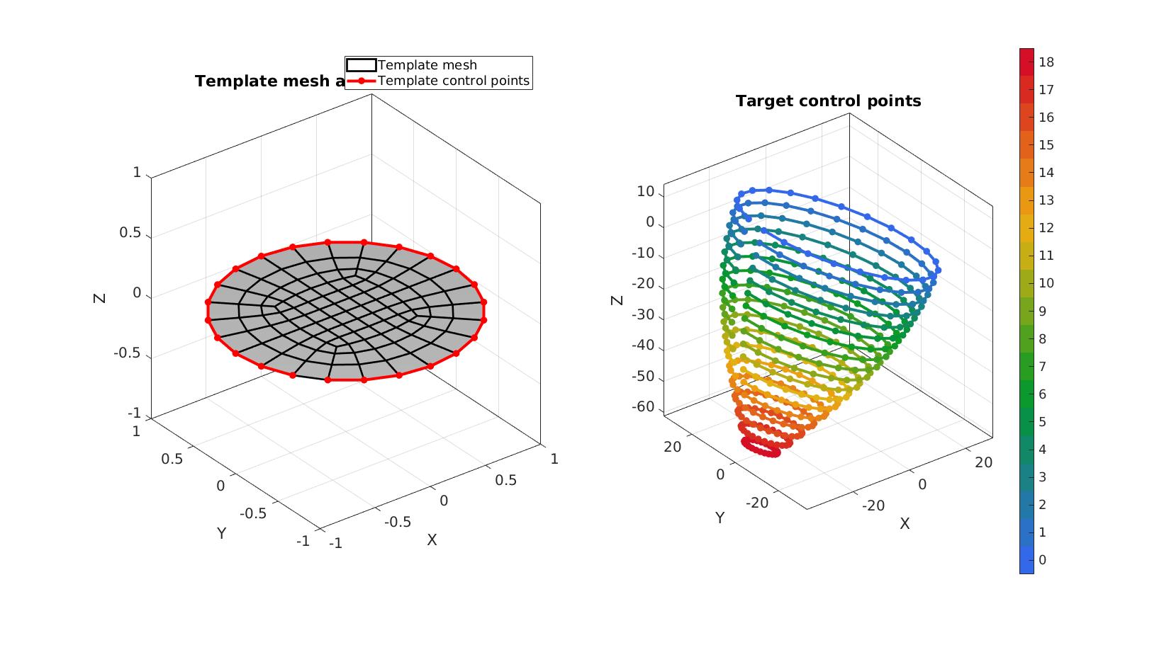
A cell containing a set of control curves is here created. The example features a tilted set of ellipse curves that vary in size.
ta=linspace(0,pi/2,numLayers);
a=30+25*(cos(ta)-1); %Radii in first ellipse direction
b=a.*1.2; %Radii in second ellipse direction
p=linspace(0,-heartHeight,numLayers); %Layer offset direction (e.g. Z-coordinate)
Q=euler2DCM([0.1*pi -0.1*pi 0.25*pi]); %Rotation

V_control_target=cell(1,numLayers);
for q=1:1:numLayers
    t = atan2(V_control_template(:,2),V_control_template(:,1));  %Angle
    V_control_target_layer=[a(q)*cos(t) b(q)*sin(t) p(q)*ones(size(t))];
    V_control_target_layer=V_control_target_layer*Q;
    V_control_target{q}=V_control_target_layer;
end
Visualize template mesh and control points
cFigure;
subplot(1,2,1); hold on;
title('Template mesh and control points');
hp1=gpatch(F_template,V_template,'w','k',1,edgeWidth);
hp2=plotV(V_control_template,'r.-','LineWidth',3,'MarkerSize',25);
legend([hp1 hp2],{'Template mesh','Template control points'});
axisGeom(gca,fontSize);
camlight headlight;

subplot(1,2,2); hold on;
title('Target control points');

Cp=gjet(numLayers); %Colors for curves
for q=1:1:numLayers
    hp=plotV(V_control_target{q},'k.-','LineWidth',3,'MarkerSize',25);
    hp.Color=Cp(q,:);
end

axisGeom(gca,fontSize);
camlight headlight;
colormap(Cp); caxis([0 numLayers]); icolorbar;
drawnow;
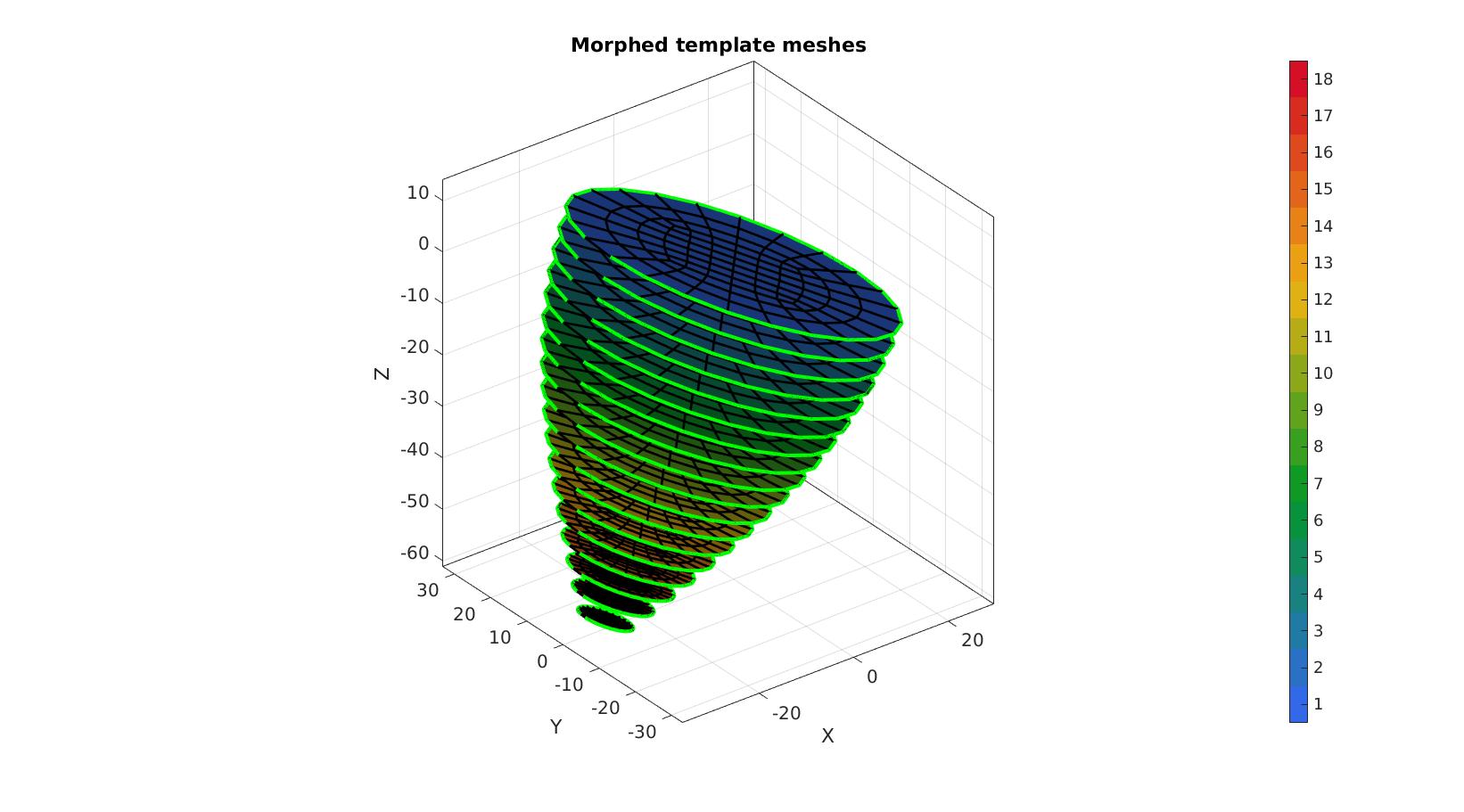
Morph template quad mesh
FT=cell(1,numLayers); %Initialize face cell
VT=cell(1,numLayers); %Initialize vertex cell
for q=1:1:numLayers %Loop over layers and process morphing individually
    %Simply copy face description from template
    FT{q}=F_template;

    %Morph vertices
    VT{q}=interpMorph(V_template,V_control_template,V_control_target{q},interpMethod,extrapMethod);
end

%Join face sets (converts cells to normal arrays)
[FT,VT,CT]=joinElementSets(FT,VT);
Visualizing morphed face sets
cFigure; hold on;
title('Morphed template meshes');
gpatch(FT,VT,CT,'k',1,edgeWidth);

for q=1:1:numLayers
    plotV(V_control_target{q},'g-','LineWidth',3,'MarkerSize',25);
end

axisGeom(gca,fontSize);
camlight headlight;
colormap gjet;  icolorbar;
drawnow;
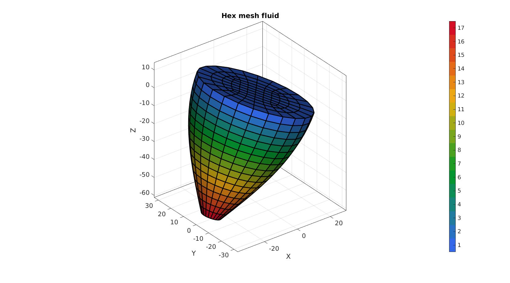
Build hexahedral elements of interior
Loop over face layers and use faces as tops/bottoms of volumetric elements.
E1=[];
C1=[];
for q=1:1:numLayers-1
    e=[FT(CT==q,:) FT(CT==q+1,:)];
    E1=[E1; e];
    C1=[C1; q*ones(size(e,1),1)];
end

[F1,CF1]=element2patch(E1,C1);
V1=VT;
Visualize interior mesh
cFigure; hold on;
title('Hex mesh fluid');

gpatch(F1,V1,CF1,'k',1,edgeWidth);
% patchNormPlot(F1,V1);

axisGeom(gca,fontSize);
camlight headlight;
colormap gjet;  icolorbar;
drawnow;
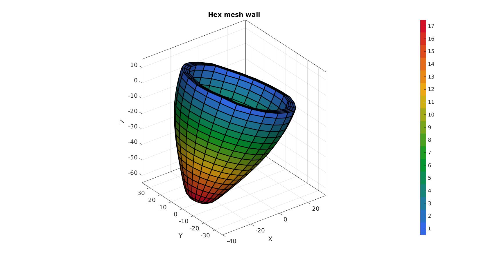
Bound wall mesh from by offsetting interior
Get boundary faces
indBoundaryFaces=tesBoundary(F1);
Fb1=F1(indBoundaryFaces,:);
Cb1=CF1(indBoundaryFaces,:);

Cb1_V=faceToVertexMeasure(Fb1,V1,Cb1);

logicSides=~all(Cb1_V(Fb1)==1,2);

Fb1_sides=Fb1(logicSides,:);
Cb1_sides=Cb1(logicSides,:);
Smooth outer mesh
indSmooth=unique(Fb1_sides(:));
[Ft,Vt]=patchCleanUnused(Fb1_sides,V1);

cPar.n=25;
cPar.Method='HC';
cPar.RigidConstraints=indB;
[Vt]=patchSmooth(Ft,Vt,[],cPar);
V1(Fb1_sides(:),:)=Vt(Ft(:),:);
Thicken mesh to form layer
[Ft,Vt]=patchCleanUnused(Fb1_sides,V1);
[E2,V2,F2_1,F2_2]=patchThick(Ft,Vt,1,layerThickness,numSteps);
C2=repmat(Cb1_sides,[numSteps,1]);
[F2,CF2]=element2patch(E2,C2);
Visualize wall mesh
cFigure; hold on;
title('Hex mesh wall');
% gpatch(Fb1_sides,V1,'kw','k',1,edgeWidth);
gpatch(F2,V2,CF2,'k',1,edgeWidth);
% patchNormPlot(F1,V1);

axisGeom(gca,fontSize);
camlight headlight;
colormap gjet;  icolorbar;
drawnow;
Join and merge wall and interior mesh
E=[E1;E2+size(V1,1)]; %Join element sets
M=[ones(size(E1,1),1); 2*ones(size(E2,1),1)]; %Create material labels for wall/interior
V=[V1;V2]; %Join node sets
C=[C1;C2]; %Join element color data
[F,CF]=element2patch(E,C);
[~,MF]=element2patch(E,M);

%Merge mesh based on faces
[F,V,ind1,ind2]=mergeVertices(F,V);

%Correct indices after merge
E=ind2(E);
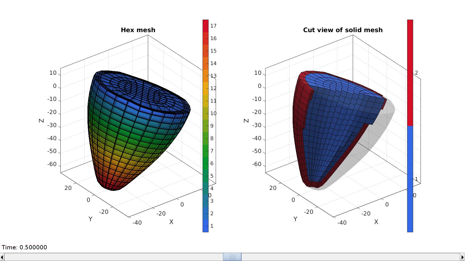
Visualize final mesh
% Create mesh structure to aid visualization
meshStruct.elements=E;
meshStruct.nodes=V;
meshStruct.faces=F;
meshStruct.elementMaterialID=M;
hFig=cFigure;

subplot(1,2,1); hold on;
title('Hex mesh');
gpatch(F,V,CF,'k',0.5,edgeWidth);
axisGeom(gca,fontSize);
camlight headlight;
colormap gjet;  icolorbar;

hs=subplot(1,2,2); hold on;
title('Cut view of solid mesh','FontSize',fontSize);
optionStruct.hFig=[hFig hs];
meshView(meshStruct,optionStruct);
axisGeom(gca,fontSize);
drawnow;
function [V_target]=interpMorph(V_template,V_control_template,V_control_target,interpMethod,extrapMethod)

U_control=V_control_target-V_control_template;

interpFunction_Ux=scatteredInterpolant(V_control_template(:,[1 2]),U_control(:,1),interpMethod,extrapMethod);
interpFunction_Uy=scatteredInterpolant(V_control_template(:,[1 2]),U_control(:,2),interpMethod,extrapMethod);
interpFunction_Uz=scatteredInterpolant(V_control_template(:,[1 2]),U_control(:,3),interpMethod,extrapMethod);

Ux_template=interpFunction_Ux(V_template(:,[1 2])); %X-displacement interpolated
Uy_template=interpFunction_Uy(V_template(:,[1 2])); %Y-displacement interpolated
Uz_template=interpFunction_Uz(V_template(:,[1 2])); %Z-displacement interpolated

V_target=V_template+[Ux_template Uy_template Uz_template];

end
GIBBON footer text
License: https://github.com/gibbonCode/GIBBON/blob/master/LICENSE
GIBBON: The Geometry and Image-based Bioengineering add-On. A toolbox for image segmentation, image-based modeling, meshing, and finite element analysis.
Copyright (C) 2006-2022 Kevin Mattheus Moerman and the GIBBON contributors
This program is free software: you can redistribute it and/or modify it under the terms of the GNU General Public License as published by the Free Software Foundation, either version 3 of the License, or (at your option) any later version.
This program is distributed in the hope that it will be useful, but WITHOUT ANY WARRANTY; without even the implied warranty of MERCHANTABILITY or FITNESS FOR A PARTICULAR PURPOSE. See the GNU General Public License for more details.
You should have received a copy of the GNU General Public License along with this program. If not, see http://www.gnu.org/licenses/.