Contents
% DEMO_febio_0086_earbud_insert_01.m
% Below is a demonstration for:
%
% * Building geometry for a thin sheet kresling structure
% * Define the sheet as shell elements
% * Defining the boundary conditions
% * Coding the febio structure
% * Running the model
% * Importing and visualizing the results
Keywords
- febio_spec version 4.0
- febio, FEBio
- earbud design
- earbud insertion
- displacement control, displacement boundary condition
- shell elements, tri3
- static, solid
- hyperelastic, Ogden
clear; close all; clc;
Plot settings
fontSize=25;
faceAlpha1=0.8;
faceAlpha2=0.3;
markerSize=40;
markerSize2=20;
lineWidth=3;
cMap=spectral(250);
Control parameters
% Path names
defaultFolder = fileparts(fileparts(mfilename('fullpath')));
savePath=fullfile(defaultFolder,'data','temp');

% Defining file names
febioFebFileNamePart='tempModel';
febioFebFileName=fullfile(savePath,[febioFebFileNamePart,'.feb']); %FEB file name
febioLogFileName=[febioFebFileNamePart,'.txt']; %FEBio log file name
febioLogFileName_disp=[febioFebFileNamePart,'_disp_out.txt']; %Log file name for exporting displacement
febioLogFileName_stress_prin=[febioFebFileNamePart,'_stress_out.txt']; %Log file name for exporting stress
febioLogFileName_strain_prin=[febioFebFileNamePart,'_strain_out.txt']; %Log file name for exporting strain
febioLogFileName_contactPressure=[febioFebFileNamePart,'_contactPressure_out.txt']; %Log file name for exporting contact pressure

%Mesh parameters
pointSpacing=1;
tetInternalVolumeFactor=10; %Make internal tets this factor larger in terms of volume, than the boundary tets

overSizeAmount=0.1;

% sphereRadiusFactor=2; %Make the sphere this factor larger in terms of radius than the radius of the ear canal
bcSupportType=2; %1 for full on back , 2 for z-support on back and full on back boundary

%Material parameter set
c1=1e-3; %Shear-modulus-like parameter
m1=6; %Material parameter setting degree of non-linearity
k_factor=100; %Bulk modulus factor
k=c1*k_factor; %Bulk modulus

% FEA control settings
numTimeSteps=10; %Number of time steps desired
max_refs=25; %Max reforms
max_ups=0; %Set to zero to use full-Newton iterations
opt_iter=10; %Optimum number of iterations
max_retries=5; %Maximum number of retires
dtmin=(1/numTimeSteps)/100; %Minimum time step size
dtmax=1/numTimeSteps; %Maximum time step size
symmetric_stiffness=0;

runMode='external';% 'internal' or 'external'

%Contact parameters
contactInitialOffset=0.1;
contactPenalty=20;
laugon=0;
minaug=1;
maxaug=10;
fric_coeff=0;
[F1,V1]=graphicsModels(14);

optionStruct.pointSpacing=pointSpacing; %Set desired point spacing
optionStruct.disp_on=0; % Turn off command window text display
[F1,V1]=ggremesh(F1,V1,optionStruct);

[Eb1,Eb_canal,Eb_outer,indBoundaryCanal,indBoundaryOuter]=getEarBoundaries(F1,V1);
indBoundaryAll=unique(Eb1);
V1(indBoundaryAll,3)=0;

%Get centroid
VE=patchCentre(Eb_canal,V1);
LE=edgeLengths(Eb_canal,V1);
Vm=sum(VE.*LE)./sum(LE);

%Centre coordinates on centroid
V1=V1-Vm(ones(size(V1,1),1),:);

%Get ear canal mean radius
VE=patchCentre(Eb_canal,V1);
RE=sqrt(sum(VE.^2,2));
Rm=sum(RE.*LE)./sum(LE);

[F2,V2]=regionTriMesh2D({V1(indBoundaryOuter,[1 2]),V1(indBoundaryCanal,[1 2])},pointSpacing,0,0);
F2=fliplr(F2);
V2(:,3)=0;

[F,V,C]=joinElementSets({F1,F2},{V1,V2});
[F,V]=mergeVertices(F,V);

[Eb1,Eb_canal,Eb_outer,indBoundaryCanal,indBoundaryOuter]=getEarBoundaries(F(C==1,:),V);
%Option set
indStart=indBoundaryCanal; %Index of the start point

%Compute distances on mesh description
d=meshDistMarch(F(C==1,:),V,indStart);
indFront=unique(F(C==1,:));
logicFront=false(size(V,1),1);
logicFront(indFront)=1;

indBudDesign=find(d<10 & logicFront);

logicCopyFaces=all(ismember(F,indBudDesign),2) & C==1;
logicCopyFaces=triSurfLogicSharpFix(F,logicCopyFaces,3);

F_base=fliplr(F(logicCopyFaces,:));
V_base=V;
[F_base,V_base]=patchCleanUnused(F_base,V_base);
Eb_base=patchBoundary(F_base);

groupOpt.outputType='label';
[Gb,~,groupSize]=tesgroup(Eb_base,groupOpt);

Eb_base1=Eb_base(Gb==1,:);
Eb_base2=Eb_base(Gb==2,:);
if max(V_base(Eb_base2(:),3))>max(V_base(Eb_base1(:),3))
    Eb_base_top=Eb_base2;
    Eb_base_bottom=Eb_base1;
else
    Eb_base_top=Eb_base1;
    Eb_base_bottom=Eb_base2;
end
indBaseTop=edgeListToCurve(Eb_base_top);
indBaseTop=indBaseTop(1:end-1);
indBaseBottom=edgeListToCurve(Eb_base_bottom);
indBaseBottom=indBaseBottom(1:end-1);

[F_base_top,V_base_top,boundaryInd_base_top]=regionTriMesh3D({V_base(indBaseTop,:)},pointSpacing,0,'natural');
[F_base_bottom,V_base_bottom,boundaryInd_base_bottom]=regionTriMesh3D({V_base(indBaseBottom,:)},pointSpacing,0,'natural');

[~,~,Nt]=patchNormal(F_base_top,V_base_top);
nf=mean(Nt,1);
nz=[0 0 1];
if dot(nz,nf)<0
    F_base_top=fliplr(F_base_top);
    Nt=-Nt;
end

[~,~,Nb]=patchNormal(F_base_bottom,V_base_bottom);
nf=mean(Nb,1);
nz=[0 0 1];
if dot(nz,nf)>0
    F_base_bottom=fliplr(F_base_bottom);
    Nb=-Nb;
end

db_top=minDist(V_base_top,mean(V_base_top,1));
dMean=mean(db_top);
[~,indMin]=minDist(V_base_top,V_base_top(boundaryInd_base_top,:));
db_top=db_top./db_top(indMin);
V_base_top=V_base_top+dMean*(Nt.*sin(acos(db_top)));

db_bottom=minDist(V_base_bottom,mean(V_base_bottom,1));
dMean=mean(db_bottom);
[~,indMin]=minDist(V_base_bottom,V_base_bottom(boundaryInd_base_bottom,:));
db_bottom=db_bottom./db_bottom(indMin);
V_base_bottom=V_base_bottom+dMean*(Nb.*sin(acos(db_bottom)));

[F_bud,V_bud,C_bud]=joinElementSets({F_base,F_base_top,F_base_bottom},{V_base,V_base_top,V_base_bottom});
[F_bud,V_bud]=mergeVertices(F_bud,V_bud);
[~,~,N_bud]=patchNormal(F_bud,V_bud);
V_bud=V_bud+overSizeAmount*N_bud;

indSmooth=unique(F_bud(C_bud~=1,:));
indRigidSmooth=unique(F_bud(C_bud==1,:));
indRigidSmooth=indRigidSmooth(~ismember(indRigidSmooth,indSmooth));

smoothOptionStruct.n=25; %Number of smoothing iterations
smoothOptionStruct.Method='HC'; %Smoothing method
smoothOptionStruct.RigidConstraints=indRigidSmooth; %Indicices for nodes to hold on to
V_bud=patchSmooth(F_bud,V_bud,[],smoothOptionStruct);

[F_bud,V_bud,C_bud]=subTriLoop(F_bud,V_bud,1);
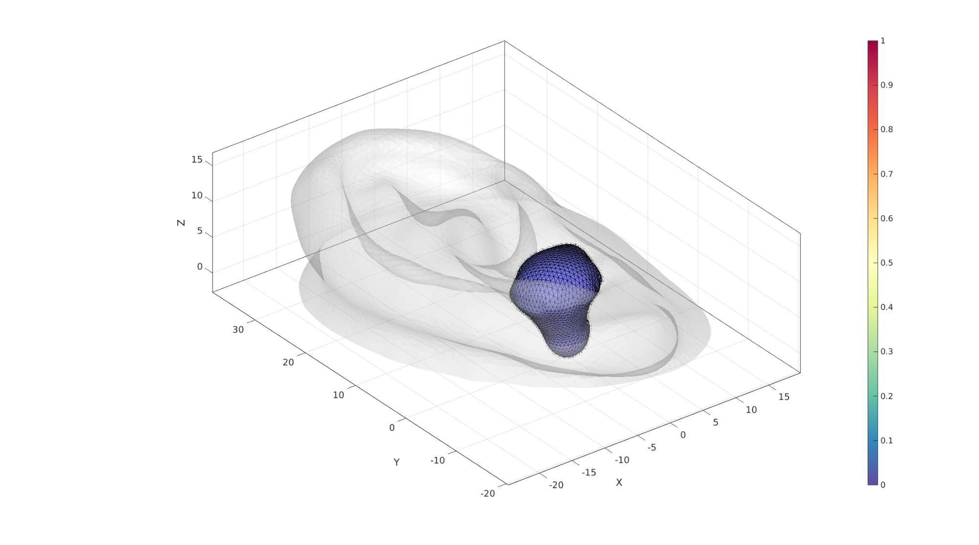
cFigure; hold on;
gpatch(F,V,'w','none',0.25);
gpatch(F_bud,V_bud,'bw','k',1);
patchNormPlot(F_bud,V_bud);
% plotV(V_bud(indRigidSmooth,:),'r.','MarkerSize',25)

% gpatch(F_base,V_base,'w','r',1,1);
% patchNormPlot(F_base,V_base);
% gedge(Eb_canal,V,'b',2);
% gedge(Eb_base_top,V,'y',3);
% plotV(V(indBudDesign,:),'r.','MarkerSize',25)
% plotV(V(indBaseTop,:),'y.-','MarkerSize',25,'LineWidth',4)
% hp=gpatch(F_base_top,V_base_top,db_top,'k',1); hp.FaceColor='Interp';
% patchNormPlot(F_base_top,V_base_top);
% hp=gpatch(F_base_bottom,V_base_bottom,db_bottom,'k',1); hp.FaceColor='Interp';
% patchNormPlot(F_base_bottom,V_base_bottom);

axisGeom; camlight headlight;
colormap spectral; colorbar;
gdrawnow;
V_regions=getInnerPoint(F,V); %Define region points
V_holes=[]; %Define hole points
[regionTetVolumes]=tetVolMeanEst(F,V); %Volume estimate for regular tets
stringOpt='-pq1.2AaY'; %Options for tetgen
Mesh using TetGen
%Create tetgen input structure
inputStruct.stringOpt=stringOpt; %Tetgen options
inputStruct.Faces=F; %Boundary faces
inputStruct.Nodes=V; %Nodes of boundary
inputStruct.faceBoundaryMarker=C;
inputStruct.regionPoints=V_regions; %Interior points for regions
inputStruct.holePoints=V_holes; %Interior points for holes
inputStruct.regionA=regionTetVolumes.*tetInternalVolumeFactor; %Desired tetrahedral volume for each region

% Mesh model using tetrahedral elements using tetGen
[meshOutput]=runTetGen(inputStruct); %Run tetGen
%%%%%%%%%%%%%%%%%%%%%%%%%%%%%%%%%%%%%%%%%%%%%
--- TETGEN Tetrahedral meshing --- 29-May-2023 11:28:24

%%%%%%%%%%%%%%%%%%%%%%%%%%%%%%%%%%%%%%%%%%%%%
--- Writing SMESH file --- 29-May-2023 11:28:24
----> Adding node field
----> Adding facet field
----> Adding holes specification
----> Adding region specification
--- Done --- 29-May-2023 11:28:24
--- Running TetGen to mesh input boundary--- 29-May-2023 11:28:24
Opening /home/kevin/DATA/Code/matlab/GIBBON/data/temp/temp.smesh.
Delaunizing vertices...
Delaunay seconds:  0.023592
Creating surface mesh ...
Surface mesh seconds:  0.006009
Recovering boundaries...
Boundary recovery seconds:  0.013388
Removing exterior tetrahedra ...
Spreading region attributes.
Exterior tets removal seconds:  0.005937
Recovering Delaunayness...
Delaunay recovery seconds:  0.00557
Refining mesh...
Refinement seconds:  0.076125
Smoothing vertices...
Mesh smoothing seconds:  0.1093
Improving mesh...
Mesh improvement seconds:  0.005001

Writing /home/kevin/DATA/Code/matlab/GIBBON/data/temp/temp.1.node.
Writing /home/kevin/DATA/Code/matlab/GIBBON/data/temp/temp.1.ele.
Writing /home/kevin/DATA/Code/matlab/GIBBON/data/temp/temp.1.face.
Writing /home/kevin/DATA/Code/matlab/GIBBON/data/temp/temp.1.edge.

Output seconds:  0.022287
Total running seconds:  0.267542

Statistics:

  Input points: 6930
  Input facets: 13860
  Input segments: 20790
  Input holes: 0
  Input regions: 1

  Mesh points: 10927
  Mesh tetrahedra: 45062
  Mesh faces: 97054
  Mesh faces on exterior boundary: 13860
  Mesh faces on input facets: 13860
  Mesh edges on input segments: 20790
  Steiner points inside domain: 3997

--- Done --- 29-May-2023 11:28:24

%%%%%%%%%%%%%%%%%%%%%%%%%%%%%%%%%%%%%%%%%%%%%
--- Importing TetGen files --- 29-May-2023 11:28:24
--- Done --- 29-May-2023 11:28:24
Access mesh output structure
E=meshOutput.elements; %The elements
V=meshOutput.nodes; %The vertices or nodes
F=meshOutput.faces; %The mesh faces (all)
CE=meshOutput.elementMaterialID; %Element material or region id
Fb=meshOutput.facesBoundary; %The boundary faces
Cb=meshOutput.boundaryMarker; %The boundary markers
Recover boundary edges
Eb=patchBoundary(Fb(Cb==2,:));
groupOpt.outputType='label';
[Gb,~,groupSize]=tesgroup(Eb,groupOpt);
[~,indMin]=min(groupSize);

Eb_canal=Eb(Gb==indMin,:);
Eb_outer=Eb(Gb~=indMin,:);
Visualization
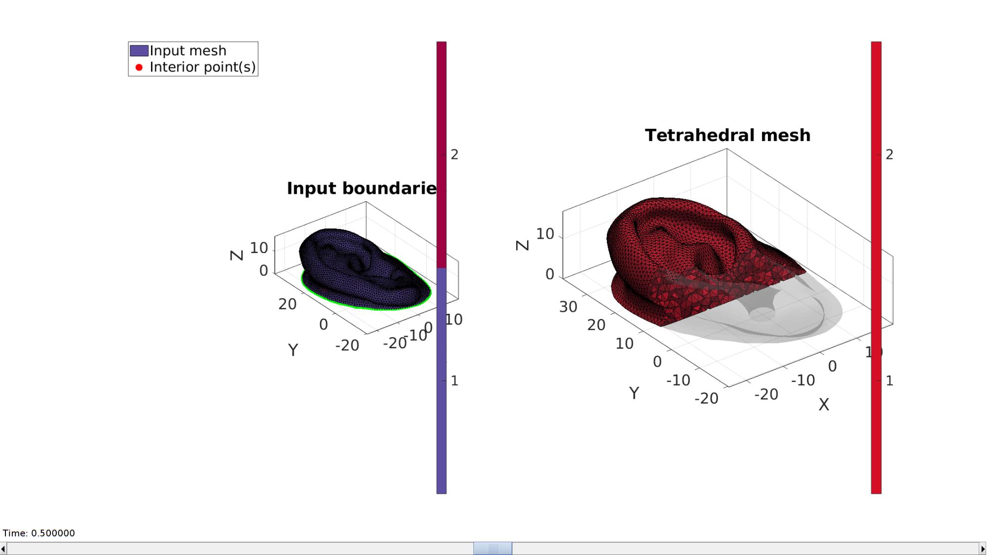
hf=cFigure;
subplot(1,2,1); hold on;
title('Input boundaries','FontSize',fontSize);
hp(1)=gpatch(Fb,V,Cb,'k',faceAlpha1);
hp(2)=plotV(V_regions,'r.','MarkerSize',markerSize);
gedge(Eb_canal,V,'y',3);
gedge(Eb_outer,V,'g',3);
legend(hp,{'Input mesh','Interior point(s)'},'Location','NorthWestOutside');
axisGeom(gca,fontSize); camlight headlight;
colormap(cMap); icolorbar;

hs=subplot(1,2,2); hold on;
title('Tetrahedral mesh','FontSize',fontSize);

% Visualizing using |meshView|
optionStructMeshView.hFig=[hf,hs];
meshView(meshOutput,optionStructMeshView);

axisGeom(gca,fontSize);
gdrawnow;

% Create spherical earbud model
%
% [F_bud,V_bud]=quadSphere(3,sphereRadiusFactor*Rm,2);
%

% Position earbud based on ray tracing
optionStruct.tolEps        = 1e-6;
optionStruct.triSide       = 0;
optionStruct.rayType       = 'ray';
optionStruct.exclusionType = 'inclusive';
optionStruct.paired        = 0;

minZ_design=min(V_bud(:,3));
V_bud(:,3)=V_bud(:,3)-min(V_bud(:,3))+max(V(:,3));

n=[0 0 -1];
[P,indIntersect,d,TUV]=triSurfRayTrace(V_bud,n(ones(size(V_bud,1),1),:),Fb,V,optionStruct);

V_bud(:,3)=V_bud(:,3)-min(V_bud(:,3))+max(P(:,3));

center_of_mass=mean(V_bud,1);

%Define applied displacement
appliedDisplacement=min(V_bud(:,3))-minZ_design;
Joining node sets
F_bud=F_bud+size(V,1); %Fixed element indices
V=[V;V_bud;]; %Combined node sets
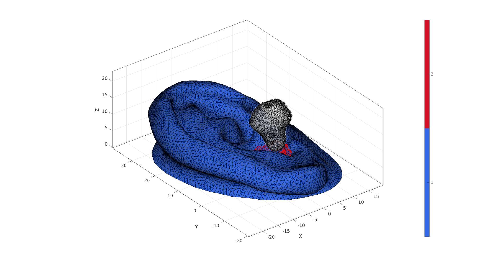
cFigure; hold on;
gpatch(Fb,V,Cb,'k');
plotV(P,'r.')
patchNormPlot(Fb,V);
gpatch(F_bud,V,'w','k',0.5);
patchNormPlot(F_bud,V);
axisGeom; camlight('headlight');
colormap gjet; icolorbar;
gdrawnow;
Define contact surfaces
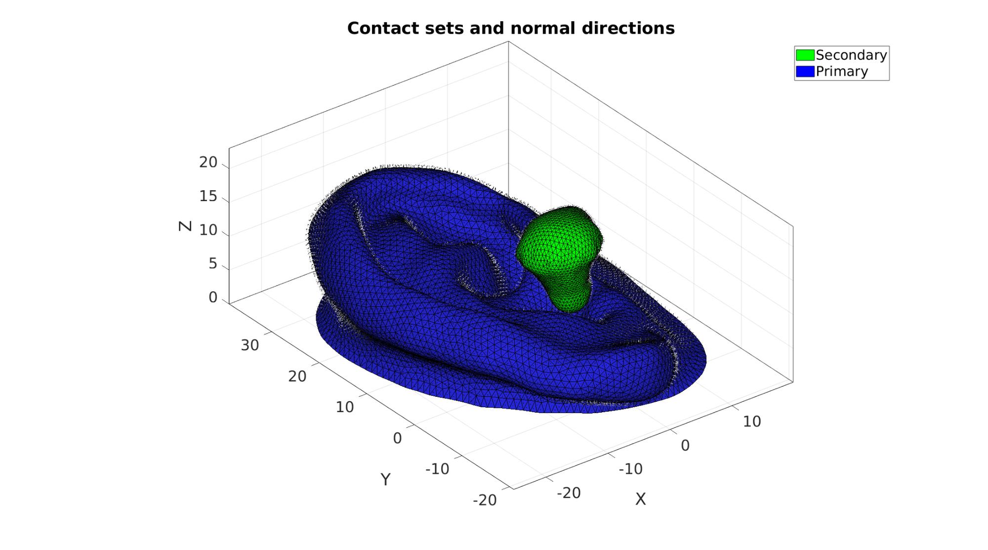
% The rigid primary surface of the sphere
F_contact_secondary=F_bud;

% The deformable secondary surface of the slab
F_contact_primary=fliplr(Fb(Cb==1,:));

% Plotting surface models
cFigure; hold on;
title('Contact sets and normal directions','FontSize',fontSize);

gpatch(Fb,V,'kw','none',faceAlpha2);
hl(1)=gpatch(F_contact_secondary,V,'g','k',1);
patchNormPlot(F_contact_secondary,V);
hl(2)=gpatch(F_contact_primary,V,'b','k',1);
patchNormPlot(F_contact_primary,V);

legend(hl,{'Secondary','Primary'});

axisGeom(gca,fontSize);
camlight headlight;
drawnow;
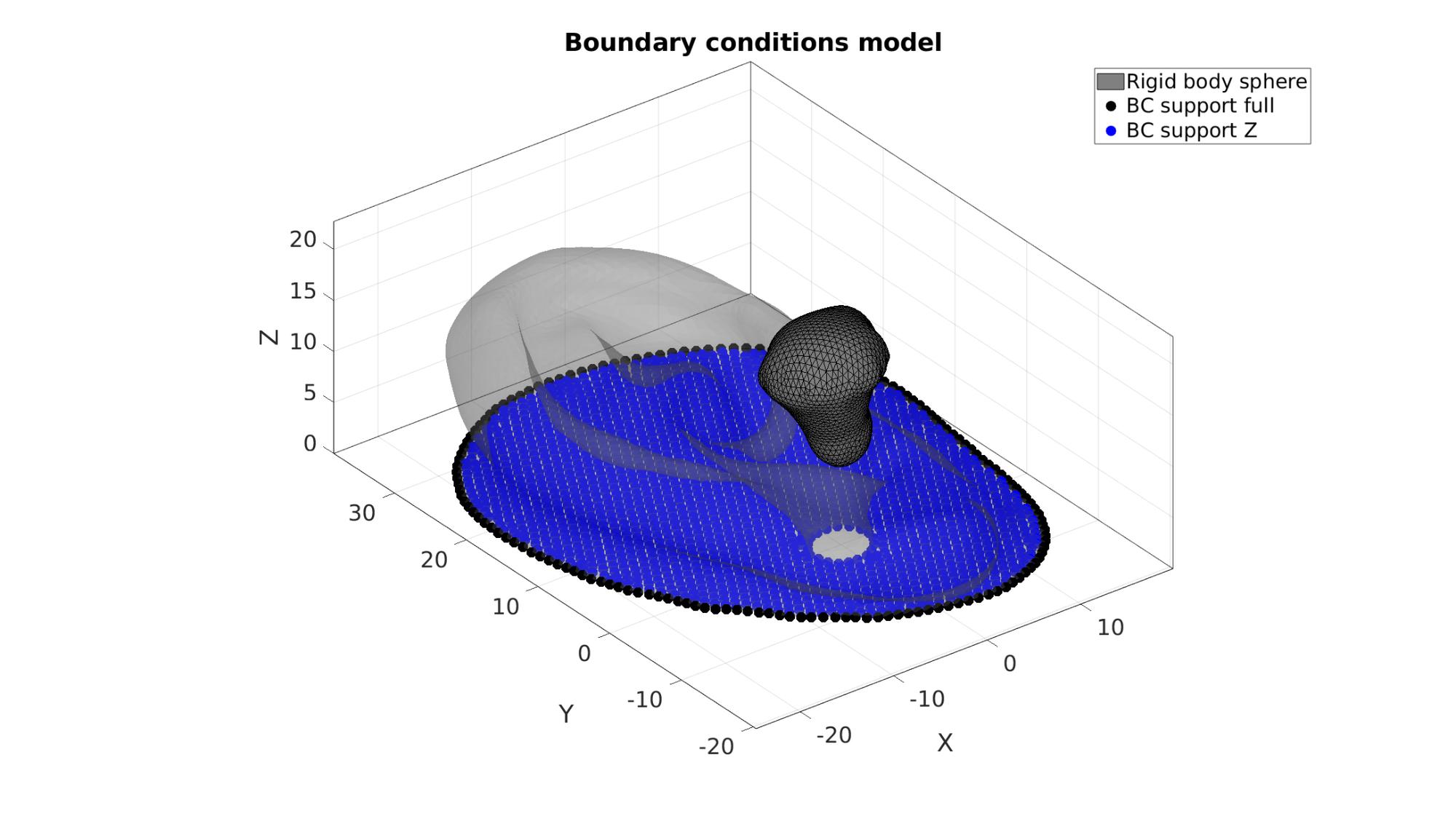
Define boundary conditions
%Supported nodes
switch bcSupportType
    case 1
        bcSupportList_full=unique(Fb(Cb==2,:));
    case 2
        bcSupportList_full=unique(Eb_outer);
        indBack=unique(Fb(Cb==2,:));
        bcSupportList_Z=indBack(~ismember(indBack,bcSupportList_full));
end
Visualize BC's
hf=cFigure;
title('Boundary conditions model','FontSize',fontSize);
xlabel('X','FontSize',fontSize); ylabel('Y','FontSize',fontSize); zlabel('Z','FontSize',fontSize);
hold on;

gpatch(Fb,V,'kw','none',faceAlpha2);
hl2(1)=gpatch(F_bud,V,'kw','k',1);

switch bcSupportType
    case 1
        hl2(2)=plotV(V(bcSupportList_full,:),'k.','MarkerSize',markerSize);
        legend(hl2,{'Rigid body sphere','BC support full'});
    case 2
        hl2(2)=plotV(V(bcSupportList_full,:),'k.','MarkerSize',markerSize);
        hl2(3)=plotV(V(bcSupportList_Z,:),'b.','MarkerSize',markerSize);
        legend(hl2,{'Rigid body sphere','BC support full','BC support Z'});
end

axisGeom(gca,fontSize);
camlight headlight;
drawnow;
Defining the FEBio input structure
See also febioStructTemplate and febioStruct2xml and the FEBio user manual.
%Get a template with default settings
[febio_spec]=febioStructTemplate;

%febio_spec version
febio_spec.ATTR.version='4.0';

%Module section
febio_spec.Module.ATTR.type='solid';

%Control section
febio_spec.Control.analysis='STATIC';
febio_spec.Control.time_steps=numTimeSteps;
febio_spec.Control.step_size=1/numTimeSteps;
febio_spec.Control.solver.max_refs=max_refs;
febio_spec.Control.solver.qn_method.max_ups=max_ups;
febio_spec.Control.solver.symmetric_stiffness=symmetric_stiffness;
febio_spec.Control.time_stepper.dtmin=dtmin;
febio_spec.Control.time_stepper.dtmax=dtmax;
febio_spec.Control.time_stepper.max_retries=max_retries;
febio_spec.Control.time_stepper.opt_iter=opt_iter;

%Material section
materialName1='Material1';
febio_spec.Material.material{1}.ATTR.name=materialName1;
febio_spec.Material.material{1}.ATTR.type='Ogden';
febio_spec.Material.material{1}.ATTR.id=1;
febio_spec.Material.material{1}.c1=c1;
febio_spec.Material.material{1}.m1=m1;
febio_spec.Material.material{1}.c2=c1;
febio_spec.Material.material{1}.m2=-m1;
febio_spec.Material.material{1}.k=k;

materialName2='Material2';
febio_spec.Material.material{2}.ATTR.name=materialName2;
febio_spec.Material.material{2}.ATTR.type='rigid body';
febio_spec.Material.material{2}.ATTR.id=2;
febio_spec.Material.material{2}.density=1;
febio_spec.Material.material{2}.center_of_mass=center_of_mass;

%Mesh section
% -> Nodes
febio_spec.Mesh.Nodes{1}.ATTR.name='nodeSet_all'; %The node set name
febio_spec.Mesh.Nodes{1}.node.ATTR.id=(1:size(V,1))'; %The node id's
febio_spec.Mesh.Nodes{1}.node.VAL=V; %The nodel coordinates

% -> Elements
partName1='Part1';
febio_spec.Mesh.Elements{1}.ATTR.name=partName1; %Name of this part
febio_spec.Mesh.Elements{1}.ATTR.type='tet4'; %Element type
febio_spec.Mesh.Elements{1}.elem.ATTR.id=(1:1:size(E,1))'; %Element id's
febio_spec.Mesh.Elements{1}.elem.VAL=E; %The element matrix

partName2='Part2';
febio_spec.Mesh.Elements{2}.ATTR.name=partName2; %Name of this part
febio_spec.Mesh.Elements{2}.ATTR.type='tri3'; %Element type
febio_spec.Mesh.Elements{2}.elem.ATTR.id=size(E,1)+(1:1:size(F_bud,1))'; %Element id's
febio_spec.Mesh.Elements{2}.elem.VAL=F_bud; %The element matrix

% -> NodeSets
nodeSetName1='bcSupportList_full';
febio_spec.Mesh.NodeSet{1}.ATTR.name=nodeSetName1;
febio_spec.Mesh.NodeSet{1}.VAL=mrow(bcSupportList_full);

if bcSupportType==2
    nodeSetName2='bcSupportList_Z';
    febio_spec.Mesh.NodeSet{2}.ATTR.name=nodeSetName2;
    febio_spec.Mesh.NodeSet{2}.VAL=mrow(bcSupportList_Z);
end

%MeshDomains section
febio_spec.MeshDomains.SolidDomain.ATTR.name=partName1;
febio_spec.MeshDomains.SolidDomain.ATTR.mat=materialName1;

febio_spec.MeshDomains.ShellDomain.ATTR.name=partName2;
febio_spec.MeshDomains.ShellDomain.ATTR.mat=materialName2;

% -> Surfaces
surfaceName1='contactSurface1';
febio_spec.Mesh.Surface{1}.ATTR.name=surfaceName1;
febio_spec.Mesh.Surface{1}.tri3.ATTR.id=(1:1:size(F_contact_primary,1))';
febio_spec.Mesh.Surface{1}.tri3.VAL=F_contact_primary;

surfaceName2='contactSurface2';
febio_spec.Mesh.Surface{2}.ATTR.name=surfaceName2;
febio_spec.Mesh.Surface{2}.tri3.ATTR.id=(1:1:size(F_contact_secondary,1))';
febio_spec.Mesh.Surface{2}.tri3.VAL=F_contact_secondary;

% -> Surface pairs
contactPairName='Contact1';
febio_spec.Mesh.SurfacePair{1}.ATTR.name=contactPairName;
febio_spec.Mesh.SurfacePair{1}.primary=surfaceName1;
febio_spec.Mesh.SurfacePair{1}.secondary=surfaceName2;

%Boundary condition section
% -> Fix boundary conditions
febio_spec.Boundary.bc{1}.ATTR.name='zero_displacement_xyz';
febio_spec.Boundary.bc{1}.ATTR.type='zero displacement';
febio_spec.Boundary.bc{1}.ATTR.node_set=nodeSetName1;
febio_spec.Boundary.bc{1}.x_dof=1;
febio_spec.Boundary.bc{1}.y_dof=1;
febio_spec.Boundary.bc{1}.z_dof=1;

if bcSupportType==2
    febio_spec.Boundary.bc{2}.ATTR.name='zero_displacement_z';
    febio_spec.Boundary.bc{2}.ATTR.type='zero displacement';
    febio_spec.Boundary.bc{2}.ATTR.node_set=nodeSetName2;
    febio_spec.Boundary.bc{2}.x_dof=0;
    febio_spec.Boundary.bc{2}.y_dof=0;
    febio_spec.Boundary.bc{2}.z_dof=1;
end
%Rigid section
% ->Rigid body fix boundary conditions
febio_spec.Rigid.rigid_bc{1}.ATTR.name='RigidFix';
febio_spec.Rigid.rigid_bc{1}.ATTR.type='rigid_fixed';
febio_spec.Rigid.rigid_bc{1}.rb=2;
febio_spec.Rigid.rigid_bc{1}.Rx_dof=1;
febio_spec.Rigid.rigid_bc{1}.Ry_dof=1;
febio_spec.Rigid.rigid_bc{1}.Rz_dof=0;
febio_spec.Rigid.rigid_bc{1}.Ru_dof=1;
febio_spec.Rigid.rigid_bc{1}.Rv_dof=1;
febio_spec.Rigid.rigid_bc{1}.Rw_dof=1;

% ->Rigid body prescribe boundary conditions
febio_spec.Rigid.rigid_bc{2}.ATTR.name='RigidPrescribe';
febio_spec.Rigid.rigid_bc{2}.ATTR.type='rigid_displacement';
febio_spec.Rigid.rigid_bc{2}.rb=2;
febio_spec.Rigid.rigid_bc{2}.dof='z';
febio_spec.Rigid.rigid_bc{2}.value.ATTR.lc=1;
febio_spec.Rigid.rigid_bc{2}.value.VAL=-(appliedDisplacement+contactInitialOffset);
febio_spec.Rigid.rigid_bc{2}.relative=0;

%Contact section
febio_spec.Contact.contact{1}.ATTR.type='sliding-elastic';
febio_spec.Contact.contact{1}.ATTR.surface_pair=contactPairName;
febio_spec.Contact.contact{1}.two_pass=0;
febio_spec.Contact.contact{1}.laugon=laugon;
febio_spec.Contact.contact{1}.tolerance=0.2;
febio_spec.Contact.contact{1}.gaptol=0;
febio_spec.Contact.contact{1}.minaug=minaug;
febio_spec.Contact.contact{1}.maxaug=maxaug;
febio_spec.Contact.contact{1}.search_tol=0.01;
febio_spec.Contact.contact{1}.search_radius=0.1*sqrt(sum((max(V,[],1)-min(V,[],1)).^2,2));
febio_spec.Contact.contact{1}.symmetric_stiffness=0;
febio_spec.Contact.contact{1}.auto_penalty=1;
febio_spec.Contact.contact{1}.update_penalty=1;
febio_spec.Contact.contact{1}.penalty=contactPenalty;
febio_spec.Contact.contact{1}.fric_coeff=fric_coeff;

%LoadData section
% -> load_controller
febio_spec.LoadData.load_controller{1}.ATTR.name='LC_1';
febio_spec.LoadData.load_controller{1}.ATTR.id=1;
febio_spec.LoadData.load_controller{1}.ATTR.type='loadcurve';
febio_spec.LoadData.load_controller{1}.interpolate='LINEAR';
%febio_spec.LoadData.load_controller{1}.extend='CONSTANT';
febio_spec.LoadData.load_controller{1}.points.pt.VAL=[0 0; 1 1];

%Output section
% -> log file
febio_spec.Output.logfile.ATTR.file=febioLogFileName;
febio_spec.Output.logfile.node_data{1}.ATTR.file=febioLogFileName_disp;
febio_spec.Output.logfile.node_data{1}.ATTR.data='ux;uy;uz';
febio_spec.Output.logfile.node_data{1}.ATTR.delim=',';

febio_spec.Output.logfile.element_data{1}.ATTR.file=febioLogFileName_stress_prin;
febio_spec.Output.logfile.element_data{1}.ATTR.data='s1;s2;s3';
febio_spec.Output.logfile.element_data{1}.ATTR.delim=',';

febio_spec.Output.logfile.element_data{2}.ATTR.file=febioLogFileName_strain_prin;
febio_spec.Output.logfile.element_data{2}.ATTR.data='E1;E2;E3';
febio_spec.Output.logfile.element_data{2}.ATTR.delim=',';

febio_spec.Output.logfile.face_data{1}.ATTR.file=febioLogFileName_contactPressure;
febio_spec.Output.logfile.face_data{1}.ATTR.data='contact pressure';
febio_spec.Output.logfile.face_data{1}.ATTR.surface=surfaceName1;
febio_spec.Output.logfile.face_data{1}.ATTR.delim=',';
Quick viewing of the FEBio input file structure
The febView function can be used to view the xml structure in a MATLAB figure window.
febView(febio_spec); %Viewing the febio file
Exporting the FEBio input file
Exporting the febio_spec structure to an FEBio input file is done using the febioStruct2xml function.
febioStruct2xml(febio_spec,febioFebFileName); %Exporting to file and domNode
Running the FEBio analysis
To run the analysis defined by the created FEBio input file the runMonitorFEBio function is used. The input for this function is a structure defining job settings e.g. the FEBio input file name. The optional output runFlag informs the user if the analysis was run succesfully.
febioAnalysis.run_filename=febioFebFileName; %The input file name
febioAnalysis.run_logname=febioLogFileName; %The name for the log file
febioAnalysis.disp_on=1; %Display information on the command window
febioAnalysis.runMode=runMode;

[runFlag]=runMonitorFEBio(febioAnalysis);%START FEBio NOW!!!!!!!!
%%%%%%%%%%%%%%%%%%%%%%%%%%%%%%%%%%%%%%%%%%%%%%%%%%%%%%%%%%%%%%%%%%%%%%%%%%%
-------->    RUNNING/MONITORING FEBIO JOB    <-------- 29-May-2023 11:28:31
FEBio path: /home/kevin/FEBioStudio/bin/febio4
# Attempt removal of existing log files                29-May-2023 11:28:32
 * Removal succesful                                   29-May-2023 11:28:32
# Attempt removal of existing .xplt files              29-May-2023 11:28:32
 * Removal succesful                                   29-May-2023 11:28:32
# Starting FEBio...                                    29-May-2023 11:28:32
  Max. total analysis time is: Inf s
 * Waiting for log file creation                       29-May-2023 11:28:32
   Max. wait time: 30 s
 * Log file found.                                     29-May-2023 11:28:32
# Parsing log file...                                  29-May-2023 11:28:32
    number of iterations   : 1                         29-May-2023 11:28:33
    number of reformations : 1                         29-May-2023 11:28:33
------- converged at time : 0.1                        29-May-2023 11:28:33
    number of iterations   : 1                         29-May-2023 11:28:34
    number of reformations : 1                         29-May-2023 11:28:34
------- converged at time : 0.2                        29-May-2023 11:28:34
    number of iterations   : 4                         29-May-2023 11:28:36
    number of reformations : 4                         29-May-2023 11:28:36
------- converged at time : 0.3                        29-May-2023 11:28:36
    number of iterations   : 6                         29-May-2023 11:28:37
    number of reformations : 6                         29-May-2023 11:28:37
------- converged at time : 0.4                        29-May-2023 11:28:37
    number of iterations   : 5                         29-May-2023 11:28:39
    number of reformations : 5                         29-May-2023 11:28:39
------- converged at time : 0.5                        29-May-2023 11:28:39
    number of iterations   : 5                         29-May-2023 11:28:41
    number of reformations : 5                         29-May-2023 11:28:41
------- converged at time : 0.6                        29-May-2023 11:28:41
    number of iterations   : 6                         29-May-2023 11:28:42
    number of reformations : 6                         29-May-2023 11:28:42
------- converged at time : 0.7                        29-May-2023 11:28:42
    number of iterations   : 6                         29-May-2023 11:28:46
    number of reformations : 6                         29-May-2023 11:28:46
------- converged at time : 0.8                        29-May-2023 11:28:46
    number of iterations   : 6                         29-May-2023 11:28:47
    number of reformations : 6                         29-May-2023 11:28:47
------- converged at time : 0.9                        29-May-2023 11:28:47
    number of iterations   : 6                         29-May-2023 11:28:48
    number of reformations : 6                         29-May-2023 11:28:48
------- converged at time : 1                          29-May-2023 11:28:48
 Elapsed time : 0:00:16                                29-May-2023 11:28:48
 N O R M A L   T E R M I N A T I O N
# Done                                                 29-May-2023 11:28:48
%%%%%%%%%%%%%%%%%%%%%%%%%%%%%%%%%%%%%%%%%%%%%%%%%%%%%%%%%%%%%%%%%%%%%%%%%%%
Import FEBio results
if runFlag==1 %i.e. a succesful run
Importing nodal displacements from a log file
    dataStruct=importFEBio_logfile(fullfile(savePath,febioLogFileName_disp),0,1);

    %Access data
    N_disp_mat=dataStruct.data; %Displacement
    timeVec=dataStruct.time; %Time

    %Create deformed coordinate set
    V_DEF=N_disp_mat+repmat(V,[1 1 size(N_disp_mat,3)]);
Importing element principal strains from a log file
    dataStruct=importFEBio_logfile(fullfile(savePath,febioLogFileName_strain_prin),0,1);

    %Access data
    E_strain_effective=prin2effective(dataStruct.data,'strain'); %Effective strain
Importing element stress from a log file
    dataStruct=importFEBio_logfile(fullfile(savePath,febioLogFileName_stress_prin),0,1);

    %Access data
    E_stress_VM=prin2effective(dataStruct.data,'stress'); %Von Mises stress
Importing contact pressure from a log file
    dataStruct=importFEBio_logfile(fullfile(savePath,febioLogFileName_contactPressure),0,1);

    %Access data
    P_contact_pressure_F=dataStruct.data;
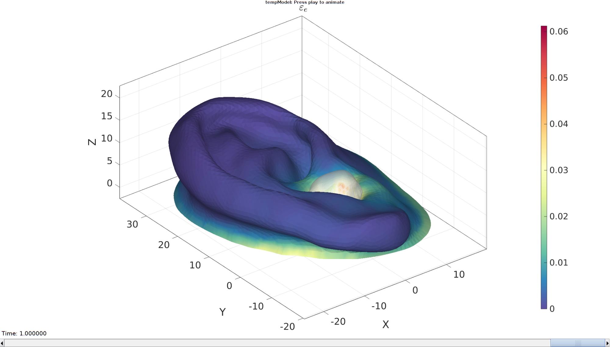
Plotting the simulated results using anim8 to visualize and animate deformations
    [CV]=faceToVertexMeasure(E,V,E_strain_effective(:,:,end));

    % Create basic view and store graphics handle to initiate animation
    hf=cFigure; %Open figure
    gtitle([febioFebFileNamePart,': Press play to animate']);
    title('$\varepsilon_{e}$','Interpreter','Latex','FontSize',fontSize);
    hp=gpatch(Fb,V_DEF(:,:,end),CV,'none',1); %Add graphics object to animate
    hp.FaceColor='interp';

    hp2=gpatch(F_bud,V_DEF(:,:,end),'w','none',0.5); %Add graphics object to animate

    axisGeom(gca,fontSize);
    colormap(cMap); colorbar;
    caxis([0 max(max(max(E_strain_effective(:,:,end))))]);
    axis(axisLim(V_DEF)); %Set axis limits statically
    camlight headlight;

    % Set up animation features
    animStruct.Time=timeVec; %The time vector
    for qt=1:1:size(N_disp_mat,3) %Loop over time increments

        [CV]=faceToVertexMeasure(E,V,E_strain_effective(:,:,qt));

        %Set entries in animation structure
        animStruct.Handles{qt}=[hp hp hp2]; %Handles of objects to animate
        animStruct.Props{qt}={'Vertices','CData','Vertices'}; %Properties of objects to animate
        animStruct.Set{qt}={V_DEF(:,:,qt),CV,V_DEF(:,:,qt)}; %Property values for to set in order to animate
    end
    anim8(hf,animStruct); %Initiate animation feature
    drawnow;
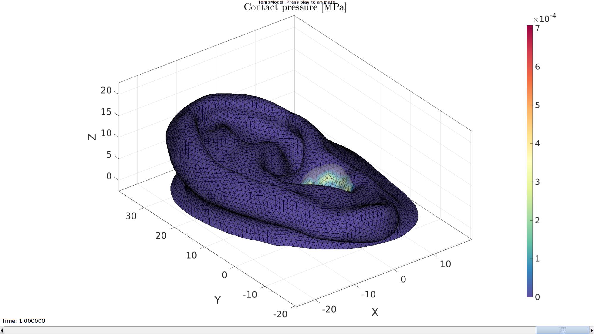
Plotting the simulated results using anim8 to visualize and animate deformations
    % Create basic view and store graphics handle to initiate animation
    hf=cFigure; %Open figure
    gtitle([febioFebFileNamePart,': Press play to animate']);
    title('Contact pressure [MPa]','Interpreter','Latex')
    %gpatch(Fb,V_DEF(:,:,end),'w','none',0.1);

    vizType='vertices'; %'faces' or 'vertices'
    switch vizType
        case 'faces'
            CP=P_contact_pressure_F(:,:,1);
            hp=gpatch(F_contact_primary,V_DEF(:,:,end),CP,'k',1); %Add graphics object to animate
        case 'vertices'
            CP=faceToVertexMeasure(F_contact_primary,V,P_contact_pressure_F(:,:,1));
            hp=gpatch(F_contact_primary,V_DEF(:,:,end),CP,'k',1); %Add graphics object to animate
            hp.FaceColor='interp';
    end

    hp2=gpatch(F_bud,V_DEF(:,:,end),'w','none',0.25); %Add graphics object to animate

    axisGeom(gca,fontSize);
    colormap(spectral(250)); colorbar;
    caxis([min(P_contact_pressure_F(:)) max(P_contact_pressure_F(:))/8]);
    axis(axisLim(V_DEF)); %Set axis limits statically
    camlight headlight;

    % Set up animation features
    animStruct.Time=timeVec; %The time vector
    for qt=1:1:size(N_disp_mat,3) %Loop over time increments

        switch vizType
            case 'faces'
                CP=P_contact_pressure_F(:,:,qt);
            case 'vertices'
                CP=faceToVertexMeasure(F_contact_primary,V,P_contact_pressure_F(:,:,qt));
        end

        %Set entries in animation structure
        animStruct.Handles{qt}=[hp hp hp2]; %Handles of objects to animate
        animStruct.Props{qt}={'Vertices','CData','Vertices'}; %Properties of objects to animate
        animStruct.Set{qt}={V_DEF(:,:,qt),CP,V_DEF(:,:,qt)}; %Property values for to set in order to animate
    end
    anim8(hf,animStruct); %Initiate animation feature
    drawnow;
end
function [Eb1,Eb_canal,Eb_outer,indBoundaryCurve1,indBoundaryCurve2]=getEarBoundaries(F1,V1)

Eb1=patchBoundary(F1);

groupOpt.outputType='label';
[Gb,~,groupSize]=tesgroup(Eb1,groupOpt);
[~,indMin]=min(groupSize);

Eb_canal=Eb1(Gb==indMin,:);
Eb_outer=Eb1(Gb~=indMin,:);

indBoundaryCurve1=edgeListToCurve(Eb_canal);
indBoundaryCurve1=indBoundaryCurve1(1:end-1)'; %Start=End for closed curve so remove double entry

indBoundaryCurve2=edgeListToCurve(Eb_outer);
indBoundaryCurve2=indBoundaryCurve2(1:end-1)'; %Start=End for closed curve so remove double entry

end

GIBBON www.gibboncode.org
Kevin Mattheus Moerman, [email protected]
GIBBON footer text
License: https://github.com/gibbonCode/GIBBON/blob/master/LICENSE
GIBBON: The Geometry and Image-based Bioengineering add-On. A toolbox for image segmentation, image-based modeling, meshing, and finite element analysis.
Copyright (C) 2006-2023 Kevin Mattheus Moerman and the GIBBON contributors
This program is free software: you can redistribute it and/or modify it under the terms of the GNU General Public License as published by the Free Software Foundation, either version 3 of the License, or (at your option) any later version.
This program is distributed in the hope that it will be useful, but WITHOUT ANY WARRANTY; without even the implied warranty of MERCHANTABILITY or FITNESS FOR A PARTICULAR PURPOSE. See the GNU General Public License for more details.
You should have received a copy of the GNU General Public License along with this program. If not, see http://www.gnu.org/licenses/.