Contents
% DEMO_febio_0081_kresling_unit_regiontrimesh_02
% Below is a demonstration for:
%
% * Building geometry for a thin sheet kresling structure
% * Thickening the sheet into a pentahedral element mesh
% * Defining the boundary conditions
% * Coding the febio structure
% * Running the model
% * Importing and visualizing the results
Keywords
- febio_spec version 4.0
- febio, FEBio
- kresling
- displacement control, displacement boundary condition
- pentahedral elements, penta6
- static, solid
- hyperelastic, Ogden
clear; close all; clc;
Plot settings
fontSize=20;
faceAlpha1=0.8; %transparency
markerSize=40; %For plotted points
markerSize2=10; %For nodes on patches
lineWidth1=1; %For meshes
lineWidth2=2; %For boundary edges
cMap=spectral(250); %colormap
Control parameters
%Geometry parameters
np=6; %Number of points in the circle e.g. 6
r=20; %Inner radius of Kresling cylinder
layerThickness=0.5;
thickenMethod=1; %1=scale inner to outter, 2=use normal directions
addMirrored=1;
cornerBiteRadius=0;
a=360/np; % Derive alpha
b=a/2; %Set beta
H=((a/180)*pi*r)/2*tand(60); %Height of Kresling layer

%Mesh parameters
pointSpacing=1;
tolLevel=pointSpacing/100;

%BC and load settings
rigidTop=1; %Add a rigid body to the top to apply contraints to (avoids warping of top)
constrainRigidTop=1; %Constrain in terms of rotation around z-axis
appliedQuasiStrain=0.5; %Percentage height reduction
displacementMagnitude=-(appliedQuasiStrain.*H);
constrainMethod=2; %1=top/bottom faces, 2=top/bottom edges

%Material parameter set
E_youngs1=1; %Material Young's modulus
nu1=0.4; %Material Poisson's ratio

% FEA control settings
numTimeSteps=10; %Number of time steps desired
max_refs=25; %Max reforms
max_ups=0; %Set to zero to use full-Newton iterations
opt_iter=6; %Optimum number of iterations
max_retries=5; %Maximum number of retires
dtmin=(1/numTimeSteps)/100; %Minimum time step size
dtmax=(1/numTimeSteps); %Maximum time step size
runMode='external';

% Path names
defaultFolder = fileparts(fileparts(mfilename('fullpath')));
savePath=fullfile(defaultFolder,'data','temp');

% Defining file names
febioFebFileNamePart='tempModel';
febioFebFileName=fullfile(savePath,[febioFebFileNamePart,'.feb']); %FEB file name
febioLogFileName=[febioFebFileNamePart,'.txt']; %FEBio log file name
febioLogFileName_disp=[febioFebFileNamePart,'_disp_out.txt']; %Log file name for exporting displacement
febioLogFileName_stress_prin=[febioFebFileNamePart,'_stress_prin_out.txt']; %Log file name for exporting principal stress
febioLogFileName_force=[febioFebFileNamePart,'_force_out.txt']; %Log file name for exporting force
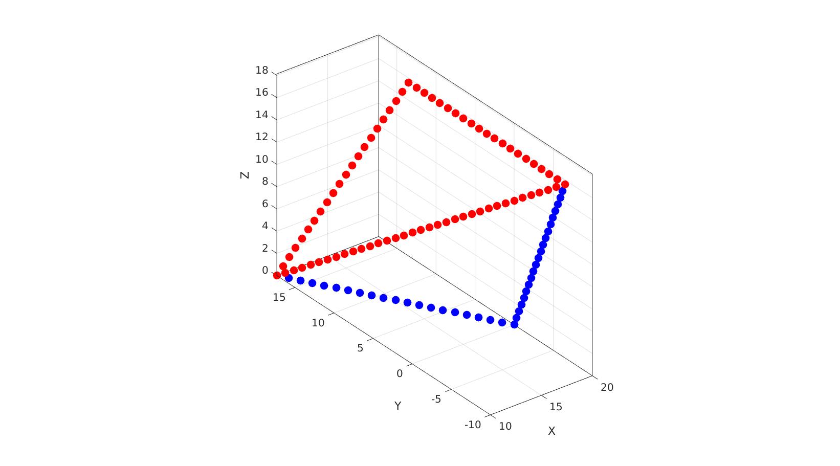
%Creating coordinates on circle
t=linspace(0,a,2)';

%Coordinates
x=r*cosd(t);
y=r*sind(t);
z=zeros(size(x));

V1=[x y z]; %Vertices
nr=vecnormalize(V1(1,:));

%Create second layer as shifted up
V2=V1;
V2(:,3)=H;

%Now rotate second later around Z axis
R=euler2DCM([0 0 (b/180)*pi]);
V2=V2*R;

Vt1=[V1; V2(1,:)];
Vt2=[V2; V1(2,:)];

if cornerBiteRadius>0
    [Vt1]=biteCorner(Vt1,cornerBiteRadius);
    [Vt2]=biteCorner(Vt2,cornerBiteRadius);
end

Vt1=evenlySpaceCurve(Vt1,pointSpacing,'linear',1,1:1:size(Vt1,1));
Vt2=evenlySpaceCurve(Vt2,pointSpacing,'linear',1,1:1:size(Vt2,1));
cFigure; hold on;

plotV(Vt1,'b.','markerSize',markerSize);
plotV(Vt2,'r.','markerSize',markerSize);

axisGeom; camlight headlight;
gdrawnow;
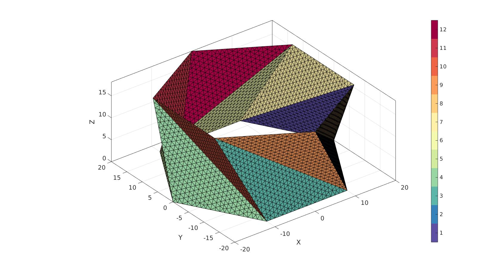
%Defining a region and control parameters (See also |regionTriMesh2D|)
resampleCurveOpt=0;
interpMethod='linear'; %or 'natural'
[Ft1,Vt1]=regionTriMesh3D({Vt1},pointSpacing,resampleCurveOpt,interpMethod);
nm=mean(patchNormal(Ft1,Vt1),1);
if dot(nm,nr)<0
    Ft1=fliplr(Ft1);
end

[Ft2,Vt2]=regionTriMesh3D({Vt2},pointSpacing,resampleCurveOpt,interpMethod);
nm=mean(patchNormal(Ft2,Vt2),1);
if dot(nm,nr)<0
    Ft2=fliplr(Ft2);
end

FT1=repmat(Ft1,np,1);
VT1=repmat(Vt1,np,1);
CT1=zeros(size(FT1,1),1);
FT2=repmat(Ft2,np,1);
VT2=repmat(Vt2,np,1);
CT2=zeros(size(FT2,1),1);
for q=1:1:np
    Rt=euler2DCM([0 0 (q-1)*(a/180)*pi]);
    VT1(1+(q-1)*size(Vt1,1):size(Vt1,1)+(q-1)*size(Vt1,1),:)=Vt1*Rt;
    VT2(1+(q-1)*size(Vt2,1):size(Vt2,1)+(q-1)*size(Vt2,1),:)=Vt2*Rt;
    FT1(1+(q-1)*size(Ft1,1):size(Ft1,1)+(q-1)*size(Ft1,1),:)=Ft1+(q-1)*size(Vt1,1);
    FT2(1+(q-1)*size(Ft2,1):size(Ft2,1)+(q-1)*size(Ft2,1),:)=Ft2+(q-1)*size(Vt2,1);
    CT1(1+(q-1)*size(Ft1,1):size(Ft1,1)+(q-1)*size(Ft1,1),:)=q;
    CT2(1+(q-1)*size(Ft2,1):size(Ft2,1)+(q-1)*size(Ft2,1),:)=q+np;
end
% VT2=VT1*R;
% VT2(:,3)=-VT2(:,3)+H;

[F,V,C]=joinElementSets({FT1,FT2},{VT1,VT2},{CT1,CT2});
cFigure; hold on;
% plotV(V1,'r.-','markerSize',markerSize,'LineWidth',lineWidth1);
% plotV(V2,'g.-','markerSize',markerSize,'LineWidth',lineWidth1);
% plotV(V,'b.','markerSize',markerSize);
gpatch(F,V,C);
% gpatch(Ft1,Vt1,'bw');
% gpatch(Ft2,Vt2,'rw');
% gpatch(FT1,VT1,'bw');
% gpatch(FT2,VT2,'rw');
% plotV(VT1,'b.','markerSize',markerSize);
% plotV(VT2,'r.','markerSize',markerSize);
% patchNormPlot(F,V);
% plotV(V(indIni,:),'r.','markerSize',markerSize);
axisGeom; camlight headlight;
colormap(cMap); icolorbar;
gdrawnow;
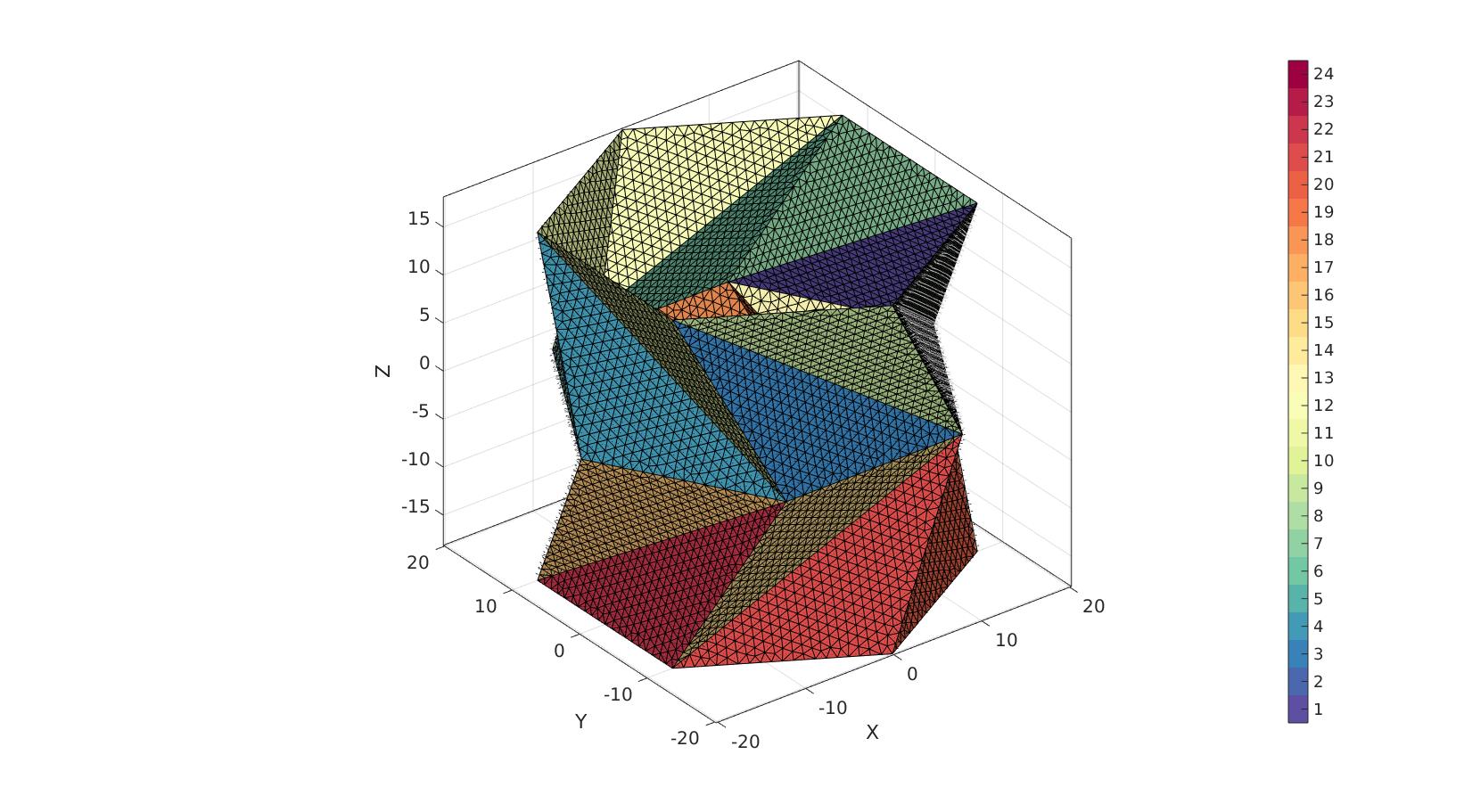
if addMirrored==1
    V2=V;
    V2(:,3)=-V2(:,3); %Mirror by inverting
    F2=fliplr(F); %To fix inversion due to mirror
    [F,V,C]=joinElementSets({F,F2},{V,V2},{C,C+max(C(:))});
end
[F,V]=mergeVertices(F,V);
cFigure; hold on;
% plotV(V1,'r.-','markerSize',markerSize,'LineWidth',lineWidth1);
% plotV(V2,'g.-','markerSize',markerSize,'LineWidth',lineWidth1);
% plotV(V,'b.','markerSize',markerSize);
gpatch(F,V,C);
patchNormPlot(F,V);
% plotV(V(indIni,:),'r.','markerSize',markerSize);
axisGeom; camlight headlight;
colormap(cMap); icolorbar;
gdrawnow;
Thickening mesh
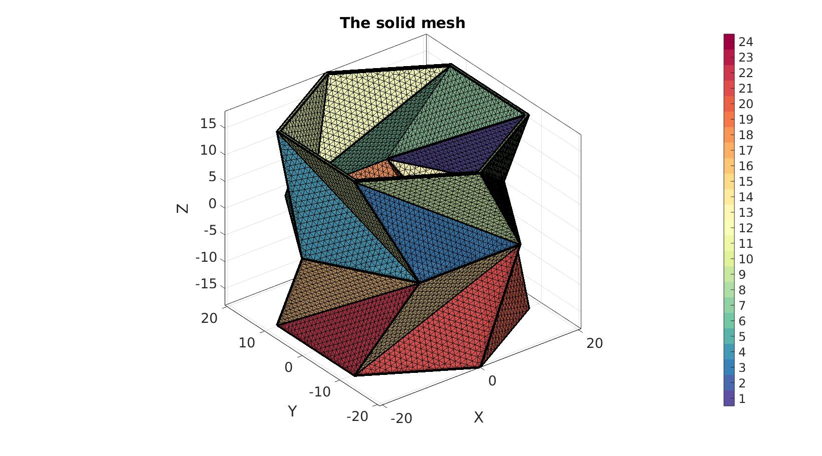
numSteps=ceil(layerThickness./pointSpacing);

switch thickenMethod
    case 1 %scale outward
        Vp1=V;
        Vp2=V;
        Vp2(:,[1 2])=(Vp2(:,[1 2])./r).*(r+(layerThickness./cosd(a/2)));

        %Get coordinates
        X=linspacen(Vp1(:,1),Vp2(:,1),numSteps+1);
        Y=linspacen(Vp1(:,2),Vp2(:,2),numSteps+1);
        Z=linspacen(Vp1(:,3),Vp2(:,3),numSteps+1);

        %Collect node set
        V=[X(:) Y(:) Z(:)];

        %Create element matrix
        E=repmat(F,[numSteps,2]);
        E_add=0:size(Vp1,1):size(Vp1,1)*(numSteps-1);
        E_add=E_add(ones(size(F,1),1),:);
        E_add=E_add(:);
        E_add=E_add(:,ones(size(F,2),1));
        E_add=[E_add E_add+size(Vp1,1)];
        E=E+E_add;
    case 2 %Normal direction based
        [~,~,dirVec]=patchNormal(F,V); %Get node normal directions
        dirVec(:,3)=0; %For z directions to be zero for offsetting directions
        dirVec=vecnormalize(dirVec);
        [E,V]=patchThick(F,V,dirVec,layerThickness,numSteps);
end

C =repmat(C,numSteps,1);
[F,CF,CFT]=element2patch(E,C,'penta6');

% Get boundary faces (two sets due to pentahedra)
indb = tesBoundary(F); %Cell containing boundary face indices
Fb = {F{1}(indb{1},:),F{2}(indb{2},:)}; %Cell containing boundary faces
Cb = {CF{1}(indb{1},:),CF{2}(indb{2},:)};
CbT = {CFT{1}(indb{1},:),CFT{2}(indb{2},:)};
Eb1=patchBoundaryLabelEdges(Fb{1},V,Cb{1}); %Boundary edges for visualization
Plotting meshed model
cFigure; hold on;
title('The solid mesh','FontSize',fontSize);

gpatch(Fb,V,Cb,'k',faceAlpha1); %Boundary faces
gedge(Eb1,V,'k',4);
% patchNormPlot(Fb,V); %Visualise normal directions

% plotV(V1,'r.-','markerSize',markerSize,'LineWidth',lineWidth);
% plotV(V2,'g.-','markerSize',markerSize,'LineWidth',lineWidth);
% plotV(V,'b.','markerSize',markerSize);
% gpatch(F,V,'g','k',0.5); %All faces

colormap(cMap); icolorbar;
axisGeom(gca,fontSize);
camlight headlight;
drawnow;
Defining the boundary conditions
switch constrainMethod
    case 1
        %Finding fixed bc nodes (bottom surface)
        Fbq=Fb{2}; %Get the boundary quads
        N=patchNormal(Fbq,V);
        nz=[0 0 1];
        d=dot(N,nz(ones(size(N,1),1),:),2); %Dot product with z-vector for all boundary face quad normals
        VF=patchCentre(Fbq,V);
        logicTopFaces    = (d>0) & VF(:,3)>(max(VF(:,3))-tolLevel);
        logicBottomFaces = (d<0) & VF(:,3)<(min(VF(:,3))+tolLevel);%~logicTopFaces; %i.e. d<0;

        Fbq_top    = Fbq(logicTopFaces,:); %Top faces
        Fbq_bottom = Fbq(logicBottomFaces,:); %Bottom faces

        bcPrescribeList=unique(Fbq_top);
        bcFixList=unique(Fbq_bottom);

        if rigidTop==1
            F_rigid=Fbq_top;
            rigidFaceType='quad4';
        end
    case 2
        Fbt1=Fb{1}(CbT{1}==1,:);

        Ebt1=patchBoundary(Fbt1);
        indBoundaryInner=unique(Ebt1);

        Z=V(:,3);
        logicTopEdges    = all(Z(Ebt1)>(max(V(:,3))-tolLevel),2);
        logicBottomEdges = all(Z(Ebt1)<(min(V(:,3))+tolLevel),2);

        bcPrescribeList = unique(Ebt1(logicTopEdges,:));
        bcFixList       = unique(Ebt1(logicBottomEdges,:));

        if rigidTop==1
            %Add central point to list
            V=[V;mean(V(bcPrescribeList,:))];
            F_rigid=[Ebt1(logicTopEdges,:) size(V,1)*ones(nnz(logicTopEdges),1)];
            rigidFaceType='tri3';
        end
end
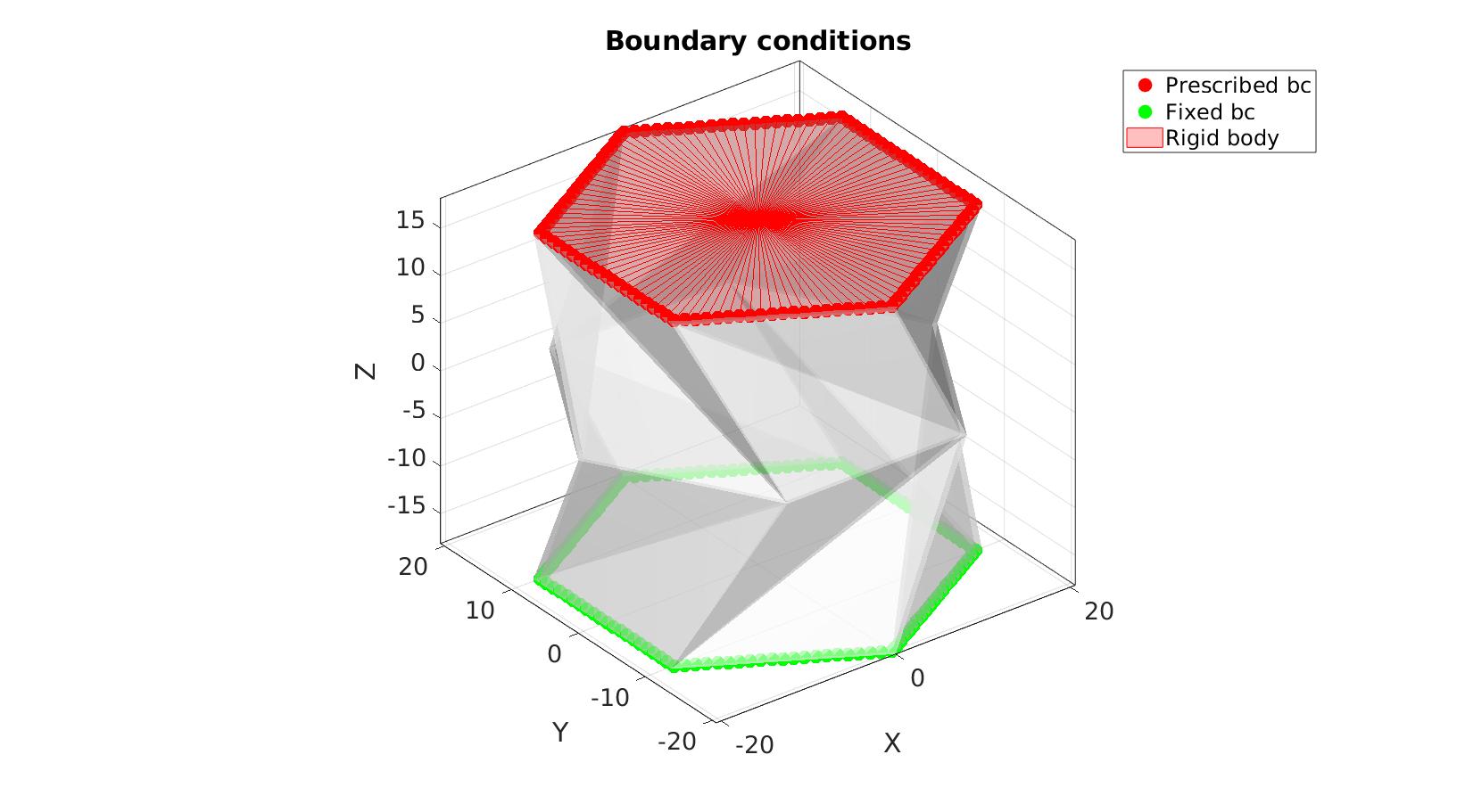
Visualizing boundary conditions. Markers plotted on the semi-transparent model denote the nodes in the various boundary condition lists.
hf=cFigure;
title('Boundary conditions','FontSize',fontSize);
xlabel('X','FontSize',fontSize); ylabel('Y','FontSize',fontSize); zlabel('Z','FontSize',fontSize);
hold on;

gpatch(Fb,V,'w','none',0.5);
hl(1)=plotV(V(bcPrescribeList,:),'r.','MarkerSize',markerSize);
hl(2)=plotV(V(bcFixList,:),'g.','MarkerSize',markerSize);
if rigidTop==1
    hl(3)=gpatch(F_rigid,V,'rw','r',0.5);
    legend(hl,{'Prescribed bc', 'Fixed bc','Rigid body'});
else
    legend(hl,{'Prescribed bc', 'Fixed bc'});
end
axisGeom(gca,fontSize);
camlight headlight;
drawnow;
Defining the FEBio input structure
See also febioStructTemplate and febioStruct2xml and the FEBio user manual.
%Get a template with default settings
[febio_spec]=febioStructTemplate;

%febio_spec version
febio_spec.ATTR.version='4.0';

%Module section
febio_spec.Module.ATTR.type='solid';

%Control section
febio_spec.Control.analysis='STATIC';
febio_spec.Control.time_steps=numTimeSteps;
febio_spec.Control.step_size=1/numTimeSteps;
febio_spec.Control.solver.max_refs=max_refs;
febio_spec.Control.solver.qn_method.max_ups=max_ups;
febio_spec.Control.time_stepper.dtmin=dtmin;
febio_spec.Control.time_stepper.dtmax=dtmax;
febio_spec.Control.time_stepper.max_retries=max_retries;
febio_spec.Control.time_stepper.opt_iter=opt_iter;

%Material section
materialName1='Material1';
febio_spec.Material.material{1}.ATTR.name=materialName1;
febio_spec.Material.material{1}.ATTR.type='neo-Hookean';
febio_spec.Material.material{1}.ATTR.id=1;
febio_spec.Material.material{1}.E=E_youngs1;
febio_spec.Material.material{1}.v=nu1;

if rigidTop==1
    materialName2='Material2';
    febio_spec.Material.material{2}.ATTR.name=materialName2;
    febio_spec.Material.material{2}.ATTR.type='rigid body';
    febio_spec.Material.material{2}.ATTR.id=2;
    febio_spec.Material.material{2}.density=1;
    febio_spec.Material.material{2}.center_of_mass=mean(V(bcPrescribeList,:),1);
end

% Mesh section
% -> Nodes

%%Area of interest
febio_spec.Mesh.Nodes{1}.ATTR.name='Object1'; %The node set name
febio_spec.Mesh.Nodes{1}.node.ATTR.id=(1:size(V,1))'; %The node id's
febio_spec.Mesh.Nodes{1}.node.VAL=V; %The nodel coordinates

% -> Elements
partName1='Part1';
febio_spec.Mesh.Elements{1}.ATTR.name=partName1; %Name of this part
febio_spec.Mesh.Elements{1}.ATTR.type='penta6'; %Element type
febio_spec.Mesh.Elements{1}.elem.ATTR.id=(1:1:size(E,1))'; %Element id's
febio_spec.Mesh.Elements{1}.elem.VAL=E; %The element matrix

if rigidTop==1
    partName2='Part2';
    febio_spec.Mesh.Elements{2}.ATTR.name=partName2; %Name of this part
    febio_spec.Mesh.Elements{2}.ATTR.type=rigidFaceType; %Element type
    febio_spec.Mesh.Elements{2}.elem.ATTR.id=size(E,1)+(1:1:size(F_rigid,1))'; %Element id's
    febio_spec.Mesh.Elements{2}.elem.VAL=F_rigid; %The element matrix
end

% -> NodeSets
nodeSetName1='bcPrescribeList1';
nodeSetName2='bcFixList2';

febio_spec.Mesh.NodeSet{1}.ATTR.name=nodeSetName1;
febio_spec.Mesh.NodeSet{1}.VAL=mrow(bcPrescribeList);

febio_spec.Mesh.NodeSet{2}.ATTR.name=nodeSetName2;
febio_spec.Mesh.NodeSet{2}.VAL=mrow(bcFixList);

%MeshDomains section
febio_spec.MeshDomains.SolidDomain.ATTR.name=partName1;
febio_spec.MeshDomains.SolidDomain.ATTR.mat=materialName1;

if rigidTop==1
    febio_spec.MeshDomains.ShellDomain.ATTR.name=partName2;
    febio_spec.MeshDomains.ShellDomain.ATTR.mat=materialName2;
end


%Boundary condition section
if rigidTop==0
    % -> Prescribe boundary conditions
    febio_spec.Boundary.bc{1}.ATTR.name='prescibed_displacement_z';
    febio_spec.Boundary.bc{1}.ATTR.type='prescribed displacement';
    febio_spec.Boundary.bc{1}.ATTR.node_set=nodeSetName1;
    febio_spec.Boundary.bc{1}.dof='z';
    febio_spec.Boundary.bc{1}.value.ATTR.lc=1;
    febio_spec.Boundary.bc{1}.value.VAL=displacementMagnitude;
    febio_spec.Boundary.bc{1}.relative=0;

    % -> Fix boundary conditions
    febio_spec.Boundary.bc{2}.ATTR.name='zero_displacement_xy';
    febio_spec.Boundary.bc{2}.ATTR.type='zero displacement';
    febio_spec.Boundary.bc{2}.ATTR.node_set=nodeSetName1;
    febio_spec.Boundary.bc{2}.x_dof=1;
    febio_spec.Boundary.bc{2}.y_dof=1;
    febio_spec.Boundary.bc{2}.z_dof=0;

    febio_spec.Boundary.bc{3}.ATTR.name='zero_displacement_xyz';
    febio_spec.Boundary.bc{3}.ATTR.type='zero displacement';
    febio_spec.Boundary.bc{3}.ATTR.node_set=nodeSetName2;
    febio_spec.Boundary.bc{3}.x_dof=1;
    febio_spec.Boundary.bc{3}.y_dof=1;
    febio_spec.Boundary.bc{3}.z_dof=1;

elseif rigidTop==1

    % -> Fix boundary conditions
    febio_spec.Boundary.bc{1}.ATTR.name='zero_displacement_xyz';
    febio_spec.Boundary.bc{1}.ATTR.type='zero displacement';
    febio_spec.Boundary.bc{1}.ATTR.node_set=nodeSetName2;
    febio_spec.Boundary.bc{1}.x_dof=1;
    febio_spec.Boundary.bc{1}.y_dof=1;
    febio_spec.Boundary.bc{1}.z_dof=1;

    %Rigid section
    % ->Rigid body fix boundary conditions
    febio_spec.Rigid.rigid_bc{1}.ATTR.name='RigidFix';
    febio_spec.Rigid.rigid_bc{1}.ATTR.type='rigid_fixed';
    febio_spec.Rigid.rigid_bc{1}.rb=2;
    if constrainRigidTop==1
        febio_spec.Rigid.rigid_bc{1}.Rx_dof=1;
        febio_spec.Rigid.rigid_bc{1}.Ry_dof=1;
        febio_spec.Rigid.rigid_bc{1}.Rz_dof=0;
        febio_spec.Rigid.rigid_bc{1}.Ru_dof=1;
        febio_spec.Rigid.rigid_bc{1}.Rv_dof=1;
        febio_spec.Rigid.rigid_bc{1}.Rw_dof=1;
    elseif constrainRigidTop==0
        febio_spec.Rigid.rigid_bc{1}.Rx_dof=1;
        febio_spec.Rigid.rigid_bc{1}.Ry_dof=1;
        febio_spec.Rigid.rigid_bc{1}.Rz_dof=0;
        febio_spec.Rigid.rigid_bc{1}.Ru_dof=1;
        febio_spec.Rigid.rigid_bc{1}.Rv_dof=1;
        febio_spec.Rigid.rigid_bc{1}.Rw_dof=0;
    end

    % ->Rigid body prescribe boundary conditions
    febio_spec.Rigid.rigid_bc{2}.ATTR.name='RigidPrescribe';
    febio_spec.Rigid.rigid_bc{2}.ATTR.type='rigid_displacement';
    febio_spec.Rigid.rigid_bc{2}.rb=2;
    febio_spec.Rigid.rigid_bc{2}.dof='z';
    febio_spec.Rigid.rigid_bc{2}.value.ATTR.lc=1;
    febio_spec.Rigid.rigid_bc{2}.value.VAL=displacementMagnitude;
    febio_spec.Rigid.rigid_bc{2}.relative=0;
end

%LoadData section
% -> load_controller
febio_spec.LoadData.load_controller{1}.ATTR.name='LC_1';
febio_spec.LoadData.load_controller{1}.ATTR.id=1;
febio_spec.LoadData.load_controller{1}.ATTR.type='loadcurve';
febio_spec.LoadData.load_controller{1}.interpolate='LINEAR';
%febio_spec.LoadData.load_controller{1}.extend='CONSTANT';
febio_spec.LoadData.load_controller{1}.points.pt.VAL=[0 0; 1 1];

%Output section
% -> log file
febio_spec.Output.logfile.ATTR.file=febioLogFileName;
febio_spec.Output.logfile.node_data{1}.ATTR.file=febioLogFileName_disp;
febio_spec.Output.logfile.node_data{1}.ATTR.data='ux;uy;uz';
febio_spec.Output.logfile.node_data{1}.ATTR.delim=',';

febio_spec.Output.logfile.node_data{2}.ATTR.file=febioLogFileName_force;
febio_spec.Output.logfile.node_data{2}.ATTR.data='Rx;Ry;Rz';
febio_spec.Output.logfile.node_data{2}.ATTR.delim=',';

febio_spec.Output.logfile.element_data{1}.ATTR.file=febioLogFileName_stress_prin;
febio_spec.Output.logfile.element_data{1}.ATTR.data='s1;s2;s3';
febio_spec.Output.logfile.element_data{1}.ATTR.delim=',';

% Plotfile section
febio_spec.Output.plotfile.compression=0;
Quick viewing of the FEBio input file structure
The febView function can be used to view the xml structure in a MATLAB figure window.
%%|febView(febio_spec); %Viewing the febio file|
Exporting the FEBio input file
Exporting the febio_spec structure to an FEBio input file is done using the febioStruct2xml function.
febioStruct2xml(febio_spec,febioFebFileName); %Exporting to file and domNode
%system(['gedit ',febioFebFileName,' &']);
Running the FEBio analysis
To run the analysis defined by the created FEBio input file the runMonitorFEBio function is used. The input for this function is a structure defining job settings e.g. the FEBio input file name. The optional output runFlag informs the user if the analysis was run succesfully.
febioAnalysis.run_filename=febioFebFileName; %The input file name
febioAnalysis.run_logname=febioLogFileName; %The name for the log file
febioAnalysis.disp_on=1; %Display information on the command window
febioAnalysis.runMode=runMode;
febioAnalysis.maxLogCheckTime=10; %Max log file checking time

[runFlag]=runMonitorFEBio(febioAnalysis);%START FEBio NOW!!!!!!!!
%%%%%%%%%%%%%%%%%%%%%%%%%%%%%%%%%%%%%%%%%%%%%%%%%%%%%%%%%%%%%%%%%%%%%%%%%%%
-------->    RUNNING/MONITORING FEBIO JOB    <-------- 04-May-2023 18:02:14
FEBio path: /home/kevin/FEBioStudio/bin/febio4
# Attempt removal of existing log files                04-May-2023 18:02:14
 * Removal succesful                                   04-May-2023 18:02:14
# Attempt removal of existing .xplt files              04-May-2023 18:02:14
 * Removal succesful                                   04-May-2023 18:02:14
# Starting FEBio...                                    04-May-2023 18:02:14
  Max. total analysis time is: Inf s
 * Waiting for log file creation                       04-May-2023 18:02:15
   Max. wait time: 10 s
 * Log file found.                                     04-May-2023 18:02:15
# Parsing log file...                                  04-May-2023 18:02:15
    number of iterations   : 4                         04-May-2023 18:02:16
    number of reformations : 4                         04-May-2023 18:02:16
------- converged at time : 0.1                        04-May-2023 18:02:16
    number of iterations   : 4                         04-May-2023 18:02:17
    number of reformations : 4                         04-May-2023 18:02:17
------- converged at time : 0.2                        04-May-2023 18:02:17
    number of iterations   : 4                         04-May-2023 18:02:17
    number of reformations : 4                         04-May-2023 18:02:17
------- converged at time : 0.3                        04-May-2023 18:02:17
    number of iterations   : 4                         04-May-2023 18:02:17
    number of reformations : 4                         04-May-2023 18:02:17
------- converged at time : 0.4                        04-May-2023 18:02:17
    number of iterations   : 4                         04-May-2023 18:02:18
    number of reformations : 4                         04-May-2023 18:02:18
------- converged at time : 0.5                        04-May-2023 18:02:18
    number of iterations   : 4                         04-May-2023 18:02:18
    number of reformations : 4                         04-May-2023 18:02:18
------- converged at time : 0.6                        04-May-2023 18:02:18
    number of iterations   : 4                         04-May-2023 18:02:19
    number of reformations : 4                         04-May-2023 18:02:19
------- converged at time : 0.7                        04-May-2023 18:02:19
    number of iterations   : 4                         04-May-2023 18:02:19
    number of reformations : 4                         04-May-2023 18:02:19
------- converged at time : 0.8                        04-May-2023 18:02:19
    number of iterations   : 4                         04-May-2023 18:02:19
    number of reformations : 4                         04-May-2023 18:02:19
------- converged at time : 0.9                        04-May-2023 18:02:19
    number of iterations   : 4                         04-May-2023 18:02:20
    number of reformations : 4                         04-May-2023 18:02:20
------- converged at time : 1                          04-May-2023 18:02:20
 Elapsed time : 0:00:05                                04-May-2023 18:02:20
 N O R M A L   T E R M I N A T I O N
# Done                                                 04-May-2023 18:02:20
%%%%%%%%%%%%%%%%%%%%%%%%%%%%%%%%%%%%%%%%%%%%%%%%%%%%%%%%%%%%%%%%%%%%%%%%%%%
Import FEBio results
if runFlag==1 %i.e. a succesful run
    % Importing nodal displacements from a log file
    dataStruct=importFEBio_logfile(fullfile(savePath,febioLogFileName_disp),0,1);

    %Access data
    N_disp_mat=dataStruct.data; %Displacement
    timeVec=dataStruct.time; %Time

    %Create deformed coordinate set
    V_DEF=N_disp_mat+repmat(V,[1 1 size(N_disp_mat,3)]);
Importing element stress from a log file
    dataStruct=importFEBio_logfile(fullfile(savePath,febioLogFileName_stress_prin),0,1);

    %Access data
    E_stress_mat=dataStruct.data;

    E_stress_mat_VM=sqrt(( (E_stress_mat(:,1,:)-E_stress_mat(:,2,:)).^2 + ...
        (E_stress_mat(:,2,:)-E_stress_mat(:,3,:)).^2 + ...
        (E_stress_mat(:,1,:)-E_stress_mat(:,3,:)).^2  )/2); %Von Mises stress
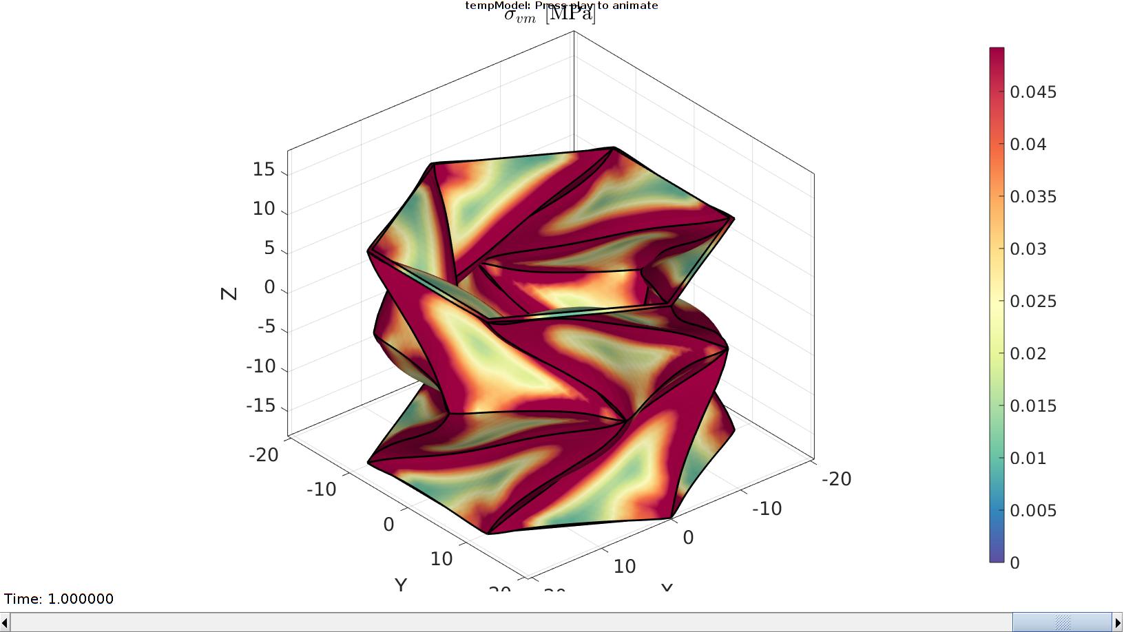
Plotting the simulated results using anim8 to visualize and animate deformations
    [CV]=faceToVertexMeasure(E,V,E_stress_mat_VM(:,:,end));

    % Create basic view and store graphics handle to initiate animation
    hf=cFigure; %Open figure  /usr/local/MATLAB/R2020a/bin/glnxa64/jcef_helper: symbol lookup error: /lib/x86_64-linux-gnu/libpango-1.0.so.0: undefined symbol: g_ptr_array_copy

    gtitle([febioFebFileNamePart,': Press play to animate']);
    title('$\sigma_{vm}$ [MPa]','Interpreter','Latex')
    hp1=gpatch(Fb,V_DEF(:,:,end),CV,'none',1,lineWidth1); %Add graphics object to animate
    hp2=gedge(Eb1,V_DEF(:,:,end),'k',lineWidth2);
    for qp=1:1:numel(hp1) %For all graphics objects e.g. triangles/quads
        hp1(qp).FaceColor='interp';
    end

    axisGeom(gca,fontSize);
    colormap(cMap); colorbar;
    caxis([min(E_stress_mat_VM(:)) max(E_stress_mat_VM(:))/2]);
    axis(axisLim(V_DEF)); %Set axis limits statically
    view(140,30);
    camlight headlight;

    % Set up animation features
    animStruct.Time=timeVec; %The time vector
    for qt=1:1:size(N_disp_mat,3) %Loop over time increments

        [CV]=faceToVertexMeasure(E,V,E_stress_mat_VM(:,:,qt));

        %Set entries in animation structure
        animStruct.Handles{qt}=[hp1(1) hp1(1) hp1(2) hp1(2) hp2]; %Handles of objects to animate
        animStruct.Props{qt}={'Vertices','CData','Vertices','CData','Vertices'}; %Properties of objects to animate
        animStruct.Set{qt}={V_DEF(:,:,qt),CV,V_DEF(:,:,qt),CV,V_DEF(:,:,qt)}; %Property values for to set in order to animate
    end
    anim8(hf,animStruct); %Initiate animation feature
    drawnow;
end
function [Vt1]=biteCorner(Vt1,cornerBiteRadius)

Et1=[1 2; 2 3; 3 1];
VEt1_1=Vt1(Et1(:,1),:);
VEt1_2=Vt1(Et1(:,2),:);
VEt1=patchCentre(Et1,Vt1);

Ut1_1m=cornerBiteRadius.*vecnormalize(VEt1-VEt1_1);
Ut1_2m=cornerBiteRadius.*vecnormalize(VEt1-VEt1_2);

Pt1_1m=VEt1_1+Ut1_1m;
Pt1_2m=VEt1_2+Ut1_2m;

Vt1=[Pt1_1m;Pt1_2m];
Ft1=[1 4 2 5 3 6];
Vt1=Vt1(Ft1,:);

end