DEMO_febio_0060_vertebrae_disc_01
Below is a demonstration for:
- Building triangulated surface geometry for a spine segment
- Defining the boundary conditions
- Coding the febio structure
- Running the model
- Importing and visualizing results
Contents
- Keywords
- Control parameters
- Get vertebra bone model
- Remeshing
- Find top and bottom surface
- Get top and bottom boundary curves
- Resample meshes so curves end up with the same number of points
- Fix curve order
- Mesh disc with tetrahedral elements
- Joining node sets
- Define boundary conditions
- Defining the FEBio input structure
- Quick viewing of the FEBio input file structure
- Exporting the FEBio input file
- Running the FEBio analysis
- Import FEBio results
Keywords
- febio_spec version 4.0
- febio, FEBio
- spine, vertebra, disc
- contact, sliding, friction
- tetrahedral elements, tet4
- hexahedral elements, hex8
- static, solid
- hyperelastic, Ogden
- displacement logfile
clear; close all; clc;
Plot settings
fontSize=15;
faceAlpha1=1;
faceAlpha2=0.3;
markerSize1=25;
markerSize2=10;
lineWidth=2;
boneColor=[1.0000    0.9500    0.8000];
discColor=[0.8500    0.5000    0.3000];
Control parameters
% Path names
defaultFolder = fileparts(fileparts(mfilename('fullpath')));
savePath=fullfile(defaultFolder,'data','temp');

% Defining file names
febioFebFileNamePart='tempModel';
febioFebFileName=fullfile(savePath,[febioFebFileNamePart,'.feb']); %FEB file name
febioLogFileName=fullfile(savePath,[febioFebFileNamePart,'.txt']); %FEBio log file name
febioLogFileName_disp=[febioFebFileNamePart,'_disp_out.txt']; %Log file name for exporting displacement
febioLogFileName_force=[febioFebFileNamePart,'_force_out.txt']; %Log file name for exporting force
febioLogFileName_strainEnergy=[febioFebFileNamePart,'_energy_out.txt']; %Log file name for exporting strain energy density

%Geometric parameters
vertebraOffset=[0 0 30];
discHeight=12;
rotAngleVert2=0;
volumeFactorDisc=2;
pointSpacing=3; %Approximate/desired node spacing
annulusFibrosusFraction=0.5;
numLayers=3;

% Material parameters
% Disc
c1_1=1; %Shear-modulus-like parameter in MPa
m1_1=2; %Material parameter setting degree of non-linearity
k_1=c1_1*100; %Bulk modulus

% FEA control settings
numTimeSteps=10; %Number of time steps desired
max_refs=25; %Max reforms
max_ups=0; %Set to zero to use full-Newton iterations
opt_iter=10; %Optimum number of iterations
max_retries=8; %Maximum number of retires
dtmin=(1/numTimeSteps)/100; %Minimum time step size
dtmax=1/numTimeSteps; %Maximum time step size
symmetric_stiffness=0;
min_residual=1e-20;

runMode='external';

%Boundary condition parameters
forceApplied=1;
displacementMagnitude=-1;
Get vertebra bone model
[F1,V1]=graphicsModels('vertebra');
rotAngle=-6;
R=euler2DCM([0 (rotAngle./180)*pi 0]);
V1=V1*R;
Remeshing
optionStructRemesh.pointSpacing=pointSpacing; %Set desired point spacing
optionStructRemesh.disp_on=1; % Turn off command window text display
[F1,V1]=ggremesh(F1,V1,optionStructRemesh);
%%%%%%%%%%%%%%%%%%%%%%%%%%%%%%%%%%%%%%%%%%%%%%%%%%%%%%%%%%%%%%%%%%%%%%%
------>  Geogram/vorpalite for resmeshing  <------ 27-Apr-2023 16:51:09
# Export mesh input file.                          27-Apr-2023 16:51:09
# Run Geomgram/vorpalite.                          27-Apr-2023 16:51:09
 ______________________________________________________________________________
|                                                                              |
| o-[config      ] Configuration file name:geogram.ini                         |
|                  Home directory:/home/kevin                                  |
| o-[I/O         ] Output = /mnt/data/MATLAB/GIBBON/data/temp/temp_out.obj     |
|                  Loading file /mnt/data/MATLAB/GIBBON/data/temp/temp.obj...  |
|                  (FP64) nb_v:7500 nb_e:0 nb_f:15000 nb_b:0 tri:1 dim:3       |
|                  Attributes on vertices: point[3]                            |
| o-[Load        ] Elapsed time: 0.01 s                                        |
   ___________________________
 _/ =====[preprocessing]===== \________________________________________________
|                                                                              |
| o-[CmdLine     ] using pre:epsilon=0(0%)                                     |
|                  using pre:max_hole_area=100                                 |
|                  using pre:min_comp_area=369.182(3%)                         |
| o-[Components  ] Nb connected components=1                                   |
|                  Mesh does not have small connected component (good)         |
| o-[Validate    ] Mesh does not have 0-area facets (good)                     |
| o-[CmdLine     ] using pre:margin=0(0%)                                      |
| o-[Pre         ] Elapsed time: 0 s                                           |
   _______________________
 _/ =====[remeshing]===== \____________________________________________________
|                                                                              |
||| o-[Newton      ] Elapsed time: 0.18s                                         |
| o-[Remesh      ] Computing RVD...                                            |
| o-[Validate    ] (FP64) nb_v:1580 nb_e:0 nb_f:3160 nb_b:0 tri:1 dim:3        |
|                  Attributes on vertices: point[3]                            |
| o-[Remesh      ] Elapsed time: 0.25 s                                        |
   ____________________________
 _/ =====[postprocessing]===== \_______________________________________________
|                                                                              |
| o-[CmdLine     ] using post:min_comp_area=369.677(3%)                        |
| o-[Components  ] Nb connected components=1                                   |
|                  Mesh does not have small connected component (good)         |
| o-[CmdLine     ] using post:max_hole_area=100                                |
|                  using post:max_deg3_dist=0.122894(0.10000000000000001%)     |
| o-[Degree3     ] Does not have any degree 3 vertex (good)                    |
| o-[Post        ] Elapsed time: 0 s                                           |
   ____________________
 _/ =====[result]===== \_______________________________________________________
|                                                                              |
| o-[FinalMesh   ] (FP64) nb_v:1580 nb_e:0 nb_f:3160 nb_b:0 tri:1 dim:3        |
|                  Attributes on vertices: point[3]                            |
| o-[I/O         ] Saving file /mnt/data/MATLAB/GIBBON/data/temp/temp_out.obj. |
|                  ..                                                          |
| o-[Total time  ] Elapsed time: 0.44 s                                        |
\______________________________________________________________________________/
# Importing remeshed geometry.                     27-Apr-2023 16:51:09
# Removing temporary files.                        27-Apr-2023 16:51:10
# Done!                                            27-Apr-2023 16:51:10
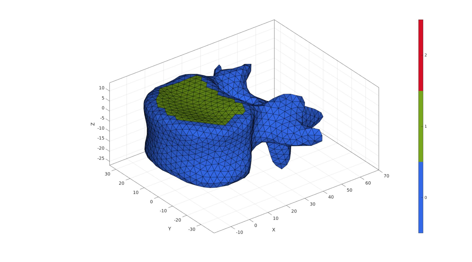
Find top and bottom surface
The below is a very basic hardcoded approach to finding (approximately) the top and bottom surfaces where the intevertebral discs would attached to the vertebra. The "detection" is based on the angle elements face with respect to the z-axis, and the distance from the origin (which lies in the middle in terms of the z-direction and in the centre of the disc attachement area in terms of the xy-direction).
angularThreshold=(25/180)*pi;
distanceThreshold=26;

V1F=patchCentre(F1,V1);

N=patchNormal(F1,V1);
nz=[0 0 1];
a=acos(dot(N,nz(ones(size(N,1),1),:),2));

D             = sqrt(sum(V1F(:,[1 2]).^2,2));
logicTop      = D<distanceThreshold & a<angularThreshold;
indNotInLogic = unique(F1(~logicTop,:));
logicTop      = logicTop & ~any(ismember(F1,indNotInLogic),2);
logicTop      = triSurfLogicSharpFix(F1,logicTop,3);

D             = sqrt(sum(V1F(:,[1 2]).^2,2));
logicBottom   = D<distanceThreshold & a>(pi-angularThreshold);
indNotInLogic = unique(F1(~logicBottom,:));
logicBottom   = logicBottom & ~any(ismember(F1,indNotInLogic),2);
logicBottom   = triSurfLogicSharpFix(F1,logicBottom,3);

C1=zeros(size(F1,1),1);
C1(logicTop)=1;
C1(logicBottom)=2;
cFigure; hold on;
gpatch(F1,V1,C1,'k',1);

axisGeom(gca,fontSize);
colormap gjet; icolorbar;
camlight('headlight');
gdrawnow;
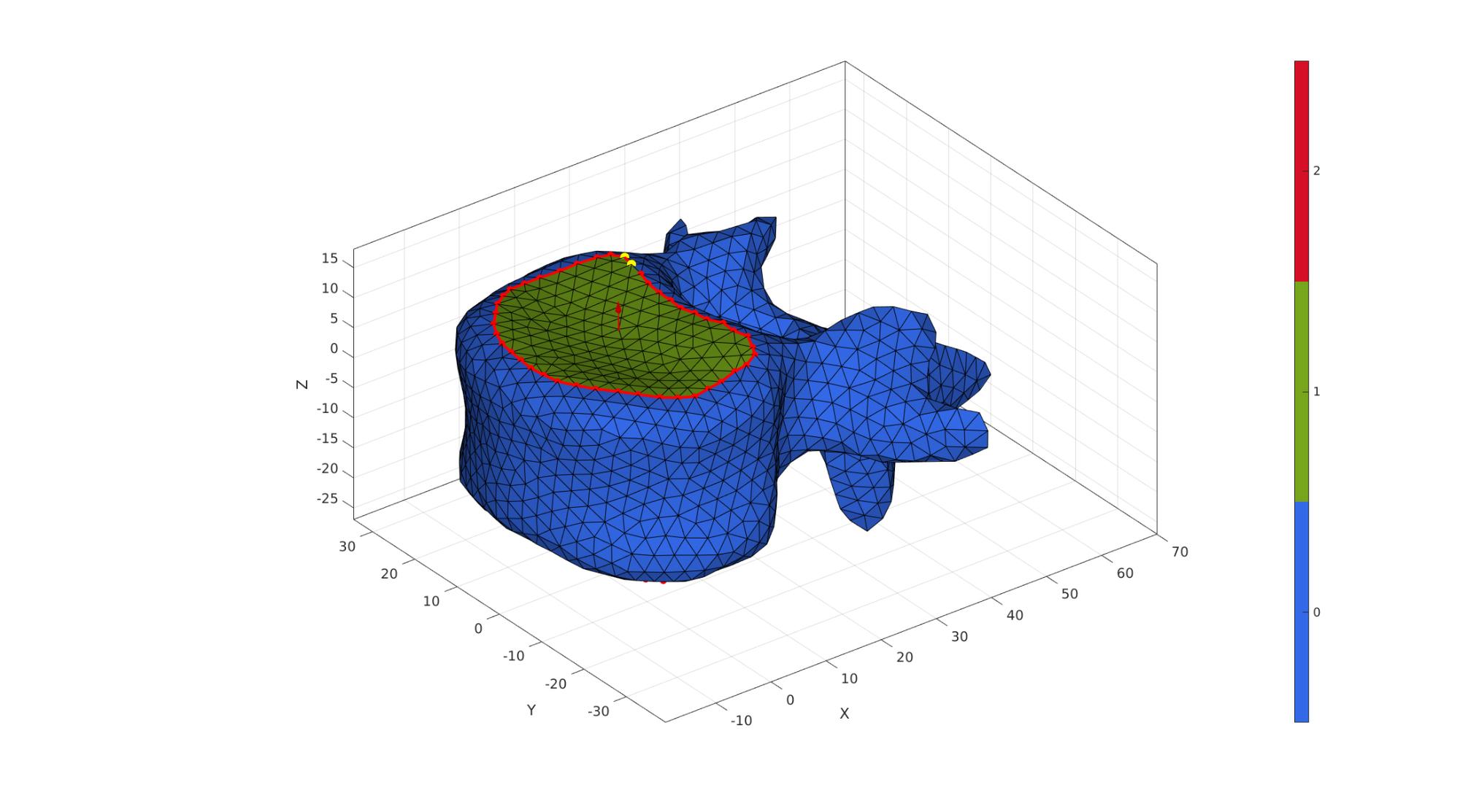
Get top and bottom boundary curves
Eb1=patchBoundary(F1(C1==1,:));
indList1=edgeListToCurve(Eb1);
indList1=indList1(1:end-1);

Eb2=patchBoundary(F1(C1==2,:));
indList2=edgeListToCurve(Eb2);
indList2=indList2(1:end-1);
Resample meshes so curves end up with the same number of points
n=[numel(indList1) numel(indList2)];
[nMax,indMax]=max(n);
nn=abs(diff(n));
switch indMax
    case 1
        [F1,V1,Eb2,C1]=triSurfSplitBoundary(F1,V1,Eb2,size(Eb2,1)+nn,C1);
        indList2=edgeListToCurve(Eb2);
        indList2=indList2(1:end-1);
    case 2
        [F1,V1,Eb1,C1]=triSurfSplitBoundary(F1,V1,Eb1,size(Eb1,1)+nn,C1);
        indList1=edgeListToCurve(Eb1);
        indList1=indList1(1:end-1);
end
Fix curve order
[~,indMin]=minDist(V1(indList1(1),:),V1(indList2,:));
if indMin>1
    indList2=[indList2(indMin:end) indList2(1:indMin-1)];
end
nc=10;
ns=50;
[V1]=smoothCurve(F1,V1,nc,ns,indList1);
[V1]=smoothCurve(F1,V1,nc,ns,indList2);

P11=mean(V1(indList1,:),1);
N11=mean(patchNormal(F1(C1==1,:),V1),1);

P12=mean(V1(indList2,:),1);
N12=-mean(patchNormal(F1(C1==2,:),V1),1);
cFigure; hold on;
gpatch(F1,V1,C1,'k',1);
% patchNormPlot(F1,V1)
plotV(V1(indList1,:),'r.-','MarkerSize',25,'LineWidth',3);
plotV(V1(indList2,:),'r.-','MarkerSize',25,'LineWidth',3);

plotV(V1(indList1(1:2),:),'y.','MarkerSize',35);
plotV(V1(indList2(1:2),:),'y.','MarkerSize',35);

% plotV(V1(indRigid,:),'c.','MarkerSize',15);
quiverVec(P11,N11,5,'r');
quiverVec(P12,N12,5,'r');

axisGeom(gca,fontSize);
colormap gjet; icolorbar;
camlight('headlight');
gdrawnow;
F2=F1;
V2=V1;
C2=C1;

R2=euler2DCM([0 (rotAngleVert2./180)*pi 0]);
V2=V2*R2;
V2=V2+vertebraOffset(ones(size(V1,1),1),:);
V2(:,3)=V2(:,3)+discHeight;

P21=mean(V2(indList1,:),1);
N21=mean(patchNormal(F2(C2==1,:),V2),1);

P22=mean(V2(indList2,:),1);
N22=-mean(patchNormal(F2(C2==2,:),V2),1);
f=discHeight/3;
p=[P11;P11+f*N11; P22-f*N22; P22];

numStepsCurve=ceil(discHeight./pointSpacing);
Vg=bezierCurve(p,numStepsCurve);

[Fds,Vds,Cds]=sweepLoft(V1(indList1,:),V2(indList2,:),N11,N12,Vg,numStepsCurve);
[~,~,Nd]=patchNormal(Fds,Vds);
CVds=faceToVertexMeasure(Fds,Vds,Cds);
CVds=CVds-min(CVds(:));
CVds=CVds./max(CVds(:));
CVds=abs(CVds-0.5);
CVds=CVds./max(CVds(:));
CVds=CVds.^2;
CVds=1-CVds;
Vds=Vds+discHeight/10*Nd.*CVds;

[Fds,Vds]=quad2tri(Fds,Vds,'a');

clear cPar;
cPar.n=5;
cPar.Method='HC';
cPar.RigidConstraints=unique(patchBoundary(Fds));
[Vds]=patchSmooth(Fds,Vds,[],cPar);

[Fd,Vd,Cd]=joinElementSets({Fds,fliplr(F2(C2==2,:)),fliplr(F1(C1==1,:))},{Vds,V2,V1});
[Fd,Vd]=patchCleanUnused(Fd,Vd);
[Fd,Vd]=mergeVertices(Fd,Vd);
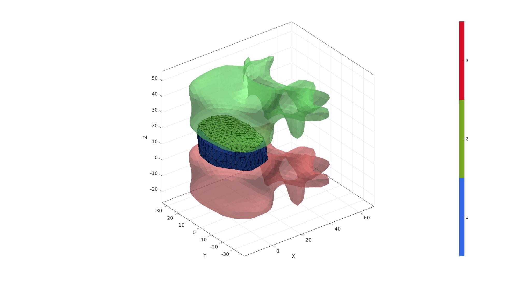
Visualize imported surfaces
cFigure; hold on;
gpatch(F1,V1,'rw','none',0.5);
gpatch(F2,V2,'gw','none',0.5);
gpatch(Fd,Vd,Cd,'k',1);

% plotV(Vg,'r.-','MarkerSize',25,'LineWidth',3);

camlight('headlight');
axisGeom(gca,fontSize);
colormap gjet; icolorbar;
gdrawnow;
Mesh disc with tetrahedral elements
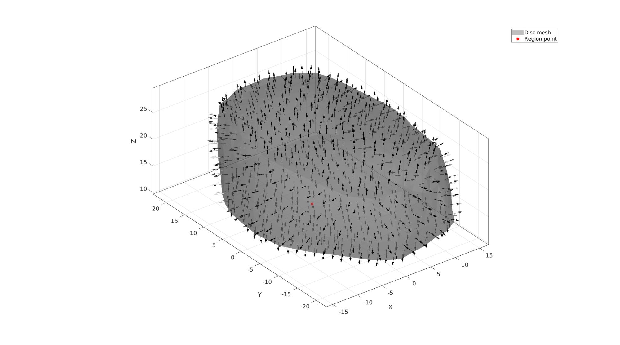
Tet meshing is based on tetgen. TetGen requires a interior points for regions to be meshed, as well as intertior points for holes.
Define region points
[V_region]=getInnerPoint(Fd,Vd);
Visualize interior points
cFigure; hold on;
hp1=gpatch(Fd,Vd,'kw','none',0.5);
patchNormPlot(Fd,Vd);
hp2=plotV(V_region,'r.','markerSize',markerSize1);
legend([hp1 hp2],{'Disc mesh','Region point'});
axisGeom(gca,fontSize);
camlight('headlight');
gdrawnow;
Mesh using tetgen
inputStruct.stringOpt='-pq1.2AaY'; %TetGen option string
inputStruct.Faces=Fd; %The faces
inputStruct.Nodes=Vd; %The vertices
inputStruct.holePoints=[]; %The hole interior points
inputStruct.faceBoundaryMarker=Cd; %Face boundary markers
inputStruct.regionPoints=V_region; %The region interior points
inputStruct.regionA=tetVolMeanEst(Fd,Vd)*volumeFactorDisc; %Volume for regular tets
Mesh model using tetrahedral elements using tetGen
[meshOutput]=runTetGen(inputStruct); %Run tetGen
%%%%%%%%%%%%%%%%%%%%%%%%%%%%%%%%%%%%%%%%%%%%%
--- TETGEN Tetrahedral meshing --- 27-Apr-2023 16:51:16

%%%%%%%%%%%%%%%%%%%%%%%%%%%%%%%%%%%%%%%%%%%%%
--- Writing SMESH file --- 27-Apr-2023 16:51:16
----> Adding node field
----> Adding facet field
----> Adding holes specification
----> Adding region specification
--- Done --- 27-Apr-2023 16:51:17
--- Running TetGen to mesh input boundary--- 27-Apr-2023 16:51:17
Opening /mnt/data/MATLAB/GIBBON/data/temp/temp.smesh.
Delaunizing vertices...
Delaunay seconds:  0.001373
Creating surface mesh ...
Surface mesh seconds:  0.000537
Recovering boundaries...
Boundary recovery seconds:  0.000744
Removing exterior tetrahedra ...
Spreading region attributes.
Exterior tets removal seconds:  0.000479
Recovering Delaunayness...
Delaunay recovery seconds:  0.00041
Refining mesh...
  515 insertions, added 310 points, 246 tetrahedra in queue.
Refinement seconds:  0.008608
Smoothing vertices...
Mesh smoothing seconds:  0.012225
Improving mesh...
Mesh improvement seconds:  0.000696

Writing /mnt/data/MATLAB/GIBBON/data/temp/temp.1.node.
Writing /mnt/data/MATLAB/GIBBON/data/temp/temp.1.ele.
Writing /mnt/data/MATLAB/GIBBON/data/temp/temp.1.face.
Writing /mnt/data/MATLAB/GIBBON/data/temp/temp.1.edge.

Output seconds:  0.007349
Total running seconds:  0.032498

Statistics:

  Input points: 387
  Input facets: 770
  Input segments: 1155
  Input holes: 0
  Input regions: 1

  Mesh points: 707
  Mesh tetrahedra: 3056
  Mesh faces: 6497
  Mesh faces on exterior boundary: 770
  Mesh faces on input facets: 770
  Mesh edges on input segments: 1155
  Steiner points inside domain: 320

--- Done --- 27-Apr-2023 16:51:17

%%%%%%%%%%%%%%%%%%%%%%%%%%%%%%%%%%%%%%%%%%%%%
--- Importing TetGen files --- 27-Apr-2023 16:51:17
--- Done --- 27-Apr-2023 16:51:17
Access model element and patch data
Fb_disc=meshOutput.facesBoundary; %Boundary faces of the disc
Cb_disc=meshOutput.boundaryMarker; %Boundary marker/color data for the disc
V_disc=meshOutput.nodes; %The vertices/nodes
E_disc=meshOutput.elements; %The tet4 elements
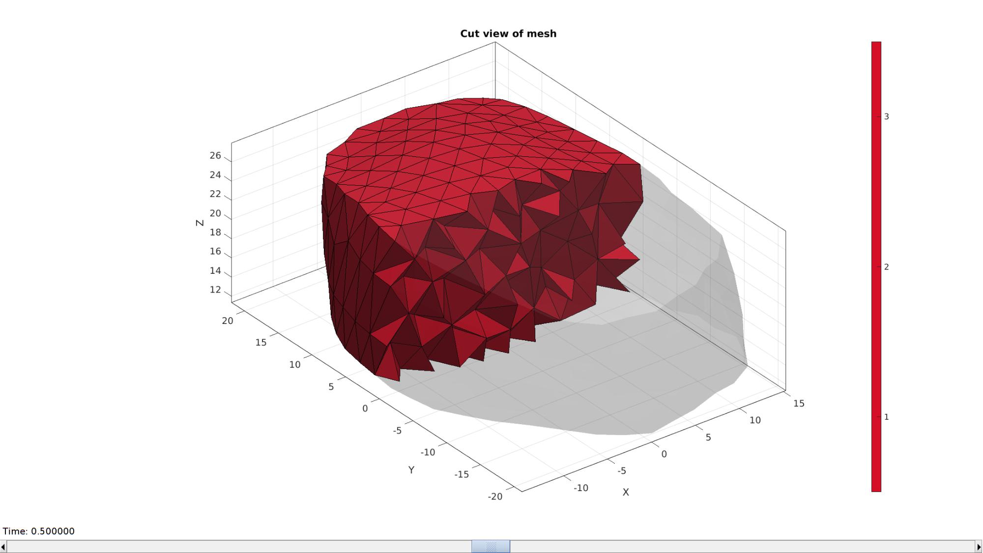
Visualizing mesh using meshView, see also anim8
meshView(meshOutput);
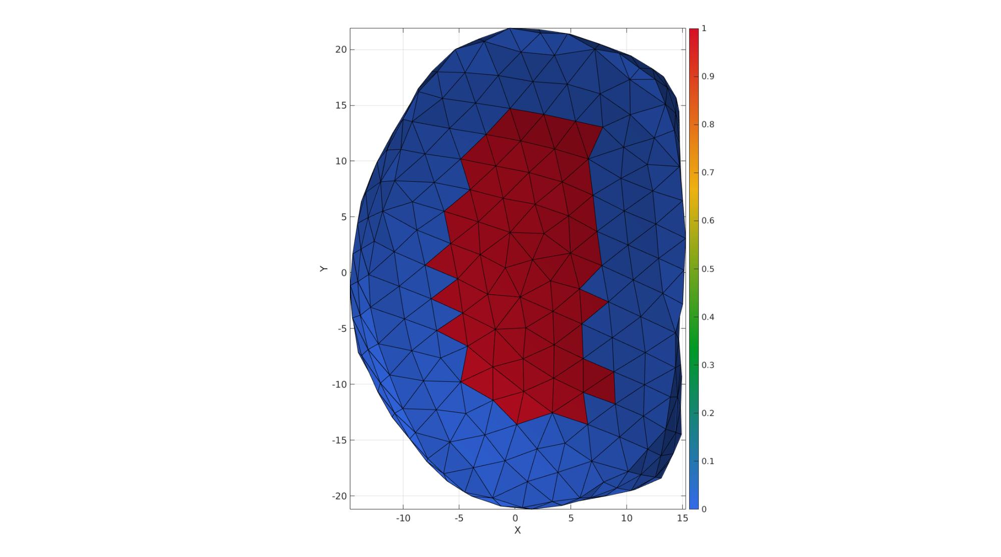
VE_disc=patchCentre(E_disc,V_disc);
Eb=patchBoundary(Fb_disc(ismember(Cb_disc,[2,3]),:));
indB=unique(Fb_disc(ismember(Cb_disc,1),:));
[D,~]=minDist(VE_disc(:,[1 2]),V_disc(indB,[1 2]));
D=D./max(D(:));
D=1-D;
logicAnnulusFibrosus=D<=annulusFibrosusFraction;
D(logicAnnulusFibrosus)=annulusFibrosusFraction;
D=D-min(D(:));
D=D./max(D(:));


[FE,CF]=element2patch(E_disc,logicAnnulusFibrosus);
cFigure;  hold on;
gpatch(FE,V_disc,CF,'k',1);

axisGeom;
camlight headlight;
view(2);
colormap gjet; colorbar;
gdrawnow;
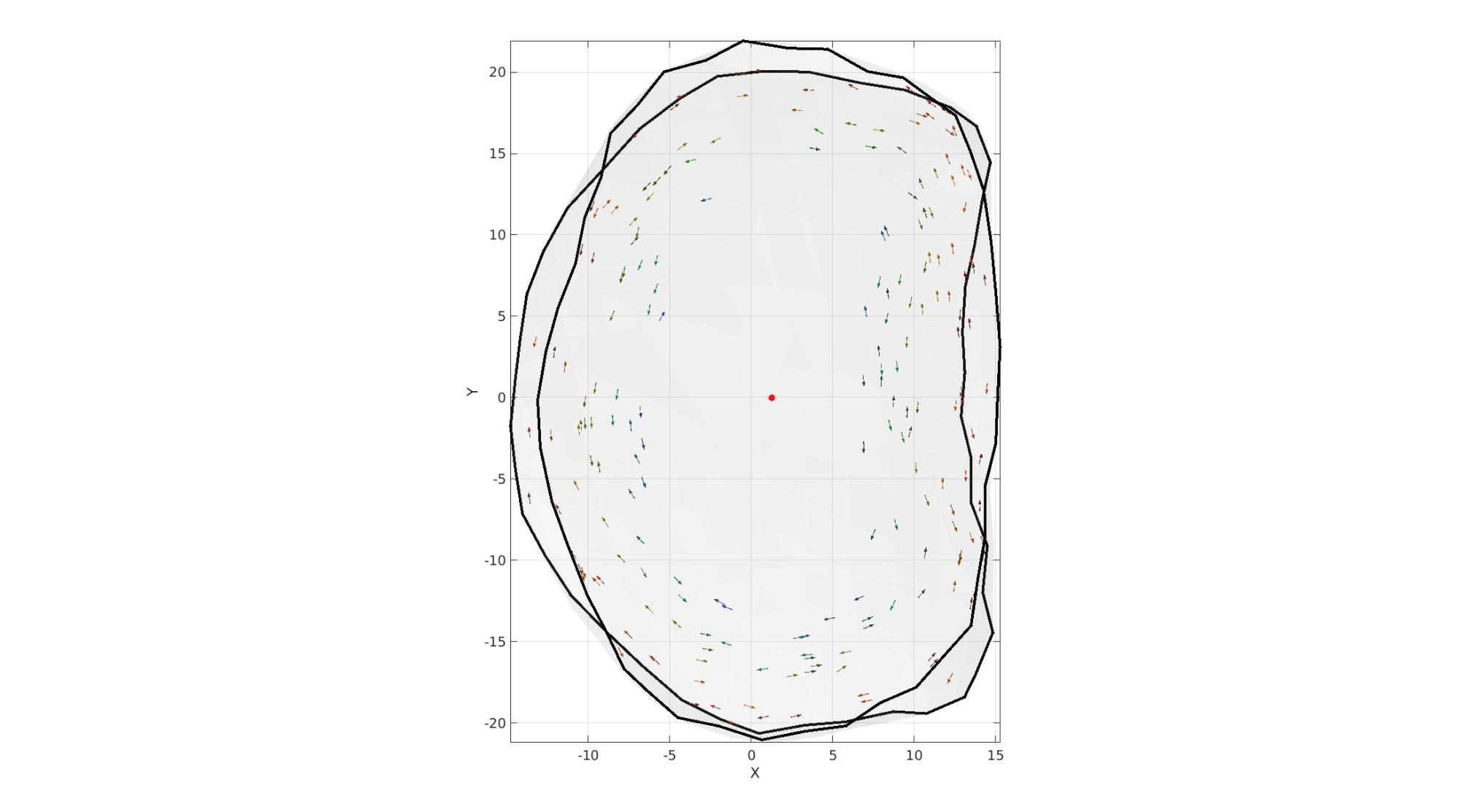
VEb=patchCentre(Eb,V_disc);
t = atan2(VEb(:,2),VEb(:,1));
T = atan2(VE_disc(:,2),VE_disc(:,1));


VEb=patchCentre(Eb,V_disc);
NE=vecnormalize(V_disc(Eb(:,1),:)-V_disc(Eb(:,2),:));
NE(:,3)=0;
NE=vecnormalize(NE);
[~,indMin]=minDist(T,t);
% z=[0 0 1];
% NFC=cross(NF,z(ones(size(NF,1),1),:),2);
NE_disc=NE(indMin,:);

% NE_disc(:,[1 2])=NE_disc(:,[1 2]).*sin(numLayers.*D(:,ones(1,2)).*2*pi);
% NE_disc(:,3)=cos(numLayers.*D.*2*pi);
% NE_disc(logicAnnulusFibrosus,:)=NaN;

logicEven=iseven(round(D.*numLayers));
NE_disc(logicEven,3)=1;
NE_disc(~logicEven,3)=-1;
NE_disc=vecnormalize(NE_disc);
NE_disc(logicAnnulusFibrosus,:)=NaN;

cFigure;  hold on;
gpatch(Fb_disc,V_disc,'w','none',0.1);
gpatch(Eb,V_disc,'none','k',1,3);
% plotV(VE_disc,'k.','MarkerSize',1);
plotV(mean(V_disc,1),'r.','MarkerSize',25);
quiverVec(VE_disc(1:10:end,:),NE_disc(1:10:end,:),1,D(1:10:end,:));
axisGeom;
camlight headlight;
view(2);
colormap gjet;
gdrawnow;
Joining node sets
V=[V_disc;V1;V2]; %Combined node sets
E1=F1+size(V_disc,1); %Fixed element indices
E2=F2+size(V_disc,1)+size(V1,1); %Fixed element indices

numDigitsMerge=6-numOrder(pointSpacing);
[~,indKeep,indFix]=unique(pround(V,numDigitsMerge),'rows');
V=V(indKeep,:);
E_disc=indFix(E_disc);
E1=indFix(E1);
E2=indFix(E2);
Fb_disc=indFix(Fb_disc);
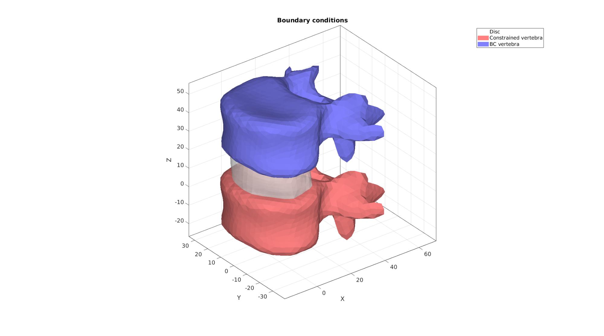
Define boundary conditions
Visualize BC's
cFigure; hold on;
title('Boundary conditions');
hp(1)=gpatch(Fb_disc,V,'w','none',0.5);
hp(2)=gpatch(E1,V,'rw','none',1);
hp(3)=gpatch(E2,V,'bw','none',1);
legend(hp,{'Disc','Constrained vertebra','BC vertebra'});

axisGeom;
camlight headlight;
gdrawnow;
Defining the FEBio input structure
See also febioStructTemplate and febioStruct2xml and the FEBio user manual.
%Get a template with default settings
[febio_spec]=febioStructTemplate;

%febio_spec version
febio_spec.ATTR.version='4.0';

%Module section
febio_spec.Module.ATTR.type='solid';

%Control section
febio_spec.Control.analysis='STATIC';
febio_spec.Control.time_steps=numTimeSteps;
febio_spec.Control.step_size=1/numTimeSteps;
febio_spec.Control.solver.max_refs=max_refs;
febio_spec.Control.solver.qn_method.max_ups=max_ups;
febio_spec.Control.time_stepper.dtmin=dtmin;
febio_spec.Control.time_stepper.dtmax=dtmax;
febio_spec.Control.time_stepper.max_retries=max_retries;
febio_spec.Control.time_stepper.opt_iter=opt_iter;

%Material section
materialName1='Material1';
febio_spec.Material.material{1}.ATTR.name=materialName1;
febio_spec.Material.material{1}.ATTR.type='Ogden';
febio_spec.Material.material{1}.ATTR.id=1;
febio_spec.Material.material{1}.c1=c1_1;
febio_spec.Material.material{1}.m1=m1_1;
febio_spec.Material.material{1}.c2=c1_1;
febio_spec.Material.material{1}.m2=-m1_1;
febio_spec.Material.material{1}.k=k_1;

materialName2='Material2';
febio_spec.Material.material{2}.ATTR.name=materialName2;
febio_spec.Material.material{2}.ATTR.type='rigid body';
febio_spec.Material.material{2}.ATTR.id=2;
febio_spec.Material.material{2}.density=1;
febio_spec.Material.material{2}.center_of_mass=mean(V(unique(E1),:),1);

materialName3='Material3';
febio_spec.Material.material{3}.ATTR.name=materialName3;
febio_spec.Material.material{3}.ATTR.type='rigid body';
febio_spec.Material.material{3}.ATTR.id=3;
febio_spec.Material.material{3}.density=1;
febio_spec.Material.material{3}.center_of_mass=mean(V(unique(E2),:),1);

% Mesh section
% -> Nodes
febio_spec.Mesh.Nodes{1}.ATTR.name='Object1'; %The node set name
febio_spec.Mesh.Nodes{1}.node.ATTR.id=(1:size(V,1))'; %The node id's
febio_spec.Mesh.Nodes{1}.node.VAL=V; %The nodel coordinates

% -> Elements
partName1='Part1';
febio_spec.Mesh.Elements{1}.ATTR.name=partName1; %Name of this part
febio_spec.Mesh.Elements{1}.ATTR.type='tet4'; %Element type
febio_spec.Mesh.Elements{1}.elem.ATTR.id=(1:1:size(E_disc,1))'; %Element id's
febio_spec.Mesh.Elements{1}.elem.VAL=E_disc; %The element matrix

partName2='Part2';
febio_spec.Mesh.Elements{2}.ATTR.name=partName2; %Name of this part
febio_spec.Mesh.Elements{2}.ATTR.type='tri3'; %Element type
febio_spec.Mesh.Elements{2}.elem.ATTR.id=size(E_disc,1)+(1:1:size(E1,1))'; %Element id's
febio_spec.Mesh.Elements{2}.elem.VAL=E1; %The element matrix

partName3='Part3';
febio_spec.Mesh.Elements{3}.ATTR.name=partName3; %Name of this part
febio_spec.Mesh.Elements{3}.ATTR.type='tri3'; %Element type
febio_spec.Mesh.Elements{3}.elem.ATTR.id=size(E_disc,1)+size(E1,1)+(1:1:size(E2,1))'; %Element id's
febio_spec.Mesh.Elements{3}.elem.VAL=E2; %The element matrix

%MeshDomains section
febio_spec.MeshDomains.SolidDomain{1}.ATTR.name=partName1;
febio_spec.MeshDomains.SolidDomain{1}.ATTR.mat=materialName1;

febio_spec.MeshDomains.ShellDomain{1}.ATTR.name=partName2;
febio_spec.MeshDomains.ShellDomain{1}.ATTR.mat=materialName2;

febio_spec.MeshDomains.ShellDomain{2}.ATTR.name=partName3;
febio_spec.MeshDomains.ShellDomain{2}.ATTR.mat=materialName3;

%Rigid section
% ->Rigid body fix boundary conditions
febio_spec.Rigid.rigid_bc{1}.ATTR.name='RigidFix1';
febio_spec.Rigid.rigid_bc{1}.ATTR.type='rigid_fixed';
febio_spec.Rigid.rigid_bc{1}.rb=2;
febio_spec.Rigid.rigid_bc{1}.Rx_dof=1;
febio_spec.Rigid.rigid_bc{1}.Ry_dof=1;
febio_spec.Rigid.rigid_bc{1}.Rz_dof=1;
febio_spec.Rigid.rigid_bc{1}.Ru_dof=1;
febio_spec.Rigid.rigid_bc{1}.Rv_dof=1;
febio_spec.Rigid.rigid_bc{1}.Rw_dof=1;

febio_spec.Rigid.rigid_bc{2}.ATTR.name='RigidFix2';
febio_spec.Rigid.rigid_bc{2}.ATTR.type='rigid_fixed';
febio_spec.Rigid.rigid_bc{2}.rb=3;
febio_spec.Rigid.rigid_bc{2}.Rx_dof=1;
febio_spec.Rigid.rigid_bc{2}.Ry_dof=1;
febio_spec.Rigid.rigid_bc{2}.Ru_dof=1;
febio_spec.Rigid.rigid_bc{2}.Rv_dof=1;
febio_spec.Rigid.rigid_bc{2}.Rw_dof=1;

% ->Rigid body prescribe boundary conditions
febio_spec.Rigid.rigid_bc{3}.ATTR.name='RigidPrescribe';
febio_spec.Rigid.rigid_bc{3}.ATTR.type='rigid_displacement';
febio_spec.Rigid.rigid_bc{3}.rb=3;
febio_spec.Rigid.rigid_bc{3}.dof='z';
febio_spec.Rigid.rigid_bc{3}.value.ATTR.lc=1;
febio_spec.Rigid.rigid_bc{3}.value.VAL=displacementMagnitude;
febio_spec.Rigid.rigid_bc{3}.relative=0;

%LoadData section
% -> load_controller
febio_spec.LoadData.load_controller{1}.ATTR.name='LC_1';
febio_spec.LoadData.load_controller{1}.ATTR.id=1;
febio_spec.LoadData.load_controller{1}.ATTR.type='loadcurve';
febio_spec.LoadData.load_controller{1}.interpolate='LINEAR';
%febio_spec.LoadData.load_controller{1}.extend='CONSTANT';
febio_spec.LoadData.load_controller{1}.points.pt.VAL=[0 0; 1 1];

%Output section
% -> log file
febio_spec.Output.logfile.ATTR.file=febioLogFileName;
febio_spec.Output.logfile.node_data{1}.ATTR.file=febioLogFileName_disp;
febio_spec.Output.logfile.node_data{1}.ATTR.data='ux;uy;uz';
febio_spec.Output.logfile.node_data{1}.ATTR.delim=',';

febio_spec.Output.logfile.node_data{2}.ATTR.file=febioLogFileName_force;
febio_spec.Output.logfile.node_data{2}.ATTR.data='Rx;Ry;Rz';
febio_spec.Output.logfile.node_data{2}.ATTR.delim=',';

febio_spec.Output.logfile.element_data{1}.ATTR.file=febioLogFileName_strainEnergy;
febio_spec.Output.logfile.element_data{1}.ATTR.data='sed';
febio_spec.Output.logfile.element_data{1}.ATTR.delim=',';
febio_spec.Output.logfile.element_data{1}.VAL=1:1:size(E_disc,1);

% Plotfile section
febio_spec.Output.plotfile.compression=0;
Quick viewing of the FEBio input file structure
The febView function can be used to view the xml structure in a MATLAB figure window.
febView(febio_spec); %Viewing the febio file
Exporting the FEBio input file
Exporting the febio_spec structure to an FEBio input file is done using the febioStruct2xml function.
febioStruct2xml(febio_spec,febioFebFileName); %Exporting to file and domNode
Running the FEBio analysis
To run the analysis defined by the created FEBio input file the runMonitorFEBio function is used. The input for this function is a structure defining job settings e.g. the FEBio input file name. The optional output runFlag informs the user if the analysis was run succesfully.
febioAnalysis.run_filename=febioFebFileName; %The input file name
febioAnalysis.run_logname=febioLogFileName; %The name for the log file
febioAnalysis.disp_on=1; %Display information on the command window
febioAnalysis.runMode=runMode;%'internal';

[runFlag]=runMonitorFEBio(febioAnalysis);%START FEBio NOW!!!!!!!!
%%%%%%%%%%%%%%%%%%%%%%%%%%%%%%%%%%%%%%%%%%%%%%%%%%%%%%%%%%%%%%%%%%%%%%%%%%%
-------->    RUNNING/MONITORING FEBIO JOB    <-------- 27-Apr-2023 16:51:26
FEBio path: /home/kevin/FEBioStudio2/bin/febio4
# Attempt removal of existing log files                27-Apr-2023 16:51:26
 * Removal succesful                                   27-Apr-2023 16:51:26
# Attempt removal of existing .xplt files              27-Apr-2023 16:51:26
 * Removal succesful                                   27-Apr-2023 16:51:26
# Starting FEBio...                                    27-Apr-2023 16:51:26
  Max. total analysis time is: Inf s
 * Waiting for log file creation                       27-Apr-2023 16:51:26
   Max. wait time: 30 s
 * Log file found.                                     27-Apr-2023 16:51:26
# Parsing log file...                                  27-Apr-2023 16:51:26
    number of iterations   : 3                         27-Apr-2023 16:51:27
    number of reformations : 3                         27-Apr-2023 16:51:27
------- converged at time : 0.1                        27-Apr-2023 16:51:27
    number of iterations   : 3                         27-Apr-2023 16:51:27
    number of reformations : 3                         27-Apr-2023 16:51:27
------- converged at time : 0.2                        27-Apr-2023 16:51:27
    number of iterations   : 3                         27-Apr-2023 16:51:27
    number of reformations : 3                         27-Apr-2023 16:51:27
------- converged at time : 0.3                        27-Apr-2023 16:51:27
    number of iterations   : 3                         27-Apr-2023 16:51:28
    number of reformations : 3                         27-Apr-2023 16:51:28
------- converged at time : 0.4                        27-Apr-2023 16:51:28
    number of iterations   : 3                         27-Apr-2023 16:51:28
    number of reformations : 3                         27-Apr-2023 16:51:28
------- converged at time : 0.5                        27-Apr-2023 16:51:28
    number of iterations   : 3                         27-Apr-2023 16:51:28
    number of reformations : 3                         27-Apr-2023 16:51:28
------- converged at time : 0.6                        27-Apr-2023 16:51:28
    number of iterations   : 3                         27-Apr-2023 16:51:28
    number of reformations : 3                         27-Apr-2023 16:51:28
------- converged at time : 0.7                        27-Apr-2023 16:51:28
    number of iterations   : 3                         27-Apr-2023 16:51:28
    number of reformations : 3                         27-Apr-2023 16:51:28
------- converged at time : 0.8                        27-Apr-2023 16:51:28
    number of iterations   : 3                         27-Apr-2023 16:51:28
    number of reformations : 3                         27-Apr-2023 16:51:28
------- converged at time : 0.9                        27-Apr-2023 16:51:28
    number of iterations   : 3                         27-Apr-2023 16:51:28
    number of reformations : 3                         27-Apr-2023 16:51:28
------- converged at time : 1                          27-Apr-2023 16:51:28
 Elapsed time : 0:00:02                                27-Apr-2023 16:51:28
 N O R M A L   T E R M I N A T I O N
# Done                                                 27-Apr-2023 16:51:28
%%%%%%%%%%%%%%%%%%%%%%%%%%%%%%%%%%%%%%%%%%%%%%%%%%%%%%%%%%%%%%%%%%%%%%%%%%%
Import FEBio results
if runFlag==1 %i.e. a succesful run
Importing nodal displacements from a log file
    dataStruct=importFEBio_logfile(fullfile(savePath,febioLogFileName_disp),0,1);

    %Access data
    N_disp_mat=dataStruct.data; %Displacement
    timeVec=dataStruct.time; %Time

    %Create deformed coordinate set
    V_DEF=N_disp_mat+repmat(V,[1 1 size(N_disp_mat,3)]);
Importing element stress from a log file
    dataStruct=importFEBio_logfile(fullfile(savePath,febioLogFileName_strainEnergy),0,1);

    %Access data
    E_sed_mat=dataStruct.data;
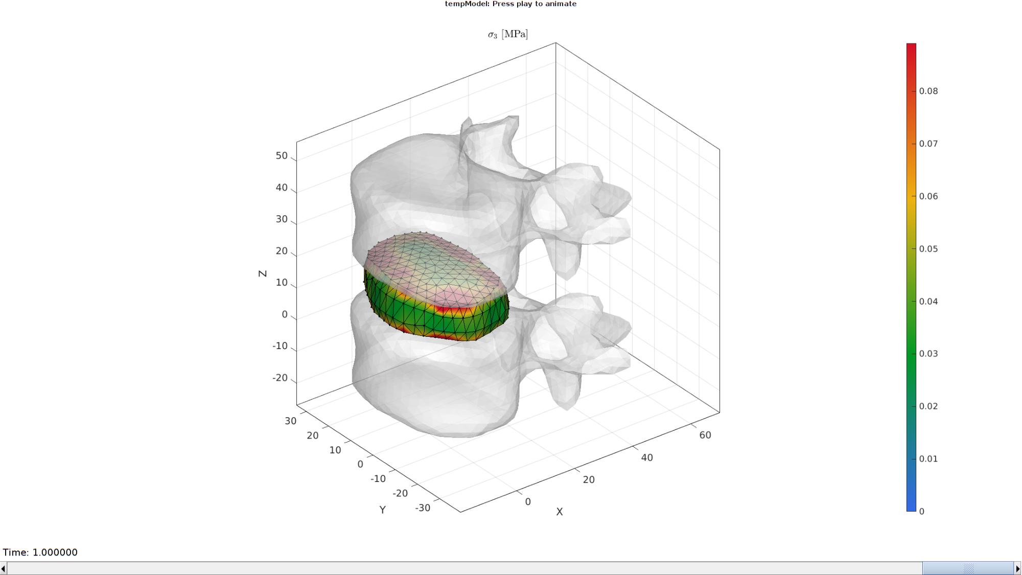
Plotting the simulated results using anim8 to visualize and animate deformations
    [CV]=faceToVertexMeasure(E_disc,V,E_sed_mat(:,:,end));

    % Create basic view and store graphics handle to initiate animation
    hf=cFigure; %Open figure
    gtitle([febioFebFileNamePart,': Press play to animate']);
    title('$\sigma_{3}$ [MPa]','Interpreter','Latex')
    hp=gpatch(Fb_disc,V_DEF(:,:,end),CV,'k',1); %Add graphics object to animate
    hp.Marker='.';
    hp.MarkerSize=markerSize2;
    hp.FaceColor='interp';

    hp2=gpatch([E1;E2],V_DEF(:,:,end),'w','none',0.5); %Add graphics object to animate

    axisGeom(gca,fontSize);
    colormap(gjet(250)); colorbar;
    caxis([0 max(E_sed_mat(:))/10]);
    axis(axisLim(V_DEF)); %Set axis limits statically
    camlight headlight;

    % Set up animation features
    animStruct.Time=timeVec; %The time vector
    for qt=1:1:size(N_disp_mat,3) %Loop over time increments

        [CV]=faceToVertexMeasure(E_disc,V,E_sed_mat(:,:,qt));

        %Set entries in animation structure
        animStruct.Handles{qt}=[hp hp hp2]; %Handles of objects to animate
        animStruct.Props{qt}={'Vertices','CData','Vertices'}; %Properties of objects to animate
        animStruct.Set{qt}={V_DEF(:,:,qt),CV,V_DEF(:,:,qt)}; %Property values for to set in order to animate
    end
    anim8(hf,animStruct); %Initiate animation feature
    drawnow;
end
function [V1]=smoothCurve(F1,V1,nc,ns,indList1)
clear cPar
cPar.n=nc;
cPar.Method='HC';
e=[(1:numel(indList1))' [(2:numel(indList1))';1]];
v=V1(indList1,:);
[v]=patchSmooth(e,v,[],cPar);
V1(indList1,:)=v;

indTouch=unique(F1(any(ismember(F1,indList1),2),:));
indTouch=unique(F1(any(ismember(F1,indTouch),2),:));
logicRigid=true(size(V1,1),1);
logicRigid(indTouch)=0;
logicRigid(indList1)=1;
indRigid=find(logicRigid);

cPar.n=ns;
cPar.Method='HC';
cPar.RigidConstraints=indRigid;
[V1]=patchSmooth(F1,V1,[],cPar);
end

GIBBON www.gibboncode.org
Kevin Mattheus Moerman, [email protected]
GIBBON footer text
License: https://github.com/gibbonCode/GIBBON/blob/master/LICENSE
GIBBON: The Geometry and Image-based Bioengineering add-On. A toolbox for image segmentation, image-based modeling, meshing, and finite element analysis.
Copyright (C) 2006-2022 Kevin Mattheus Moerman and the GIBBON contributors
This program is free software: you can redistribute it and/or modify it under the terms of the GNU General Public License as published by the Free Software Foundation, either version 3 of the License, or (at your option) any later version.
This program is distributed in the hope that it will be useful, but WITHOUT ANY WARRANTY; without even the implied warranty of MERCHANTABILITY or FITNESS FOR A PARTICULAR PURPOSE. See the GNU General Public License for more details.
You should have received a copy of the GNU General Public License along with this program. If not, see http://www.gnu.org/licenses/.