DEMO_febio_0052_breast_gap_close_01.m
Below is a demonstration for:
- Building geometry for a slab with hexahedral elements, and a triangulated sphere.
- Defining the boundary conditions
- Coding the febio structure
- Running the model
- Importing and visualizing the displacement results
Contents
- Keywords
- Plot settings
- Control parameters
- Create hemi-sphere
- Change shape of hemi-sphere to create basic breat model
- Rotate model
- Visualizing mesh using meshView, see also anim8
- Define boundary conditions
- Defining the FEBio input structure
- Quick viewing of the FEBio input file structure
- Exporting the FEBio input file
- Running the FEBio analysis
- Import FEBio results
Keywords
- febio_spec version 4.0
- febio, FEBio
- Surgery
- Breast, soft tissue
- static, solid
- hyperelastic, Ogden
- displacement logfile
- stress logfile
clear; close all; clc;
Plot settings
fontSize=15;
faceAlpha1=0.8;
faceAlpha2=0.5;
markerSize=40;
lineWidth=3;
Control parameters
% Path names
defaultFolder = fileparts(fileparts(mfilename('fullpath')));
savePath=fullfile(defaultFolder,'data','temp');

% Defining file names
febioFebFileNamePart='tempModel';
febioFebFileName=fullfile(savePath,[febioFebFileNamePart,'.feb']); %FEB file name
febioLogFileName=fullfile(savePath,[febioFebFileNamePart,'.txt']); %FEBio log file name
febioLogFileName_disp=[febioFebFileNamePart,'_disp_out.txt']; %Log file name for exporting displacement
febioLogFileName_force=[febioFebFileNamePart,'_force_out.txt']; %Log file name for exporting force

%Material parameter set
c1_1=1e-3; %Shear-modulus-like parameter
m1_1=2; %Material parameter setting degree of non-linearity
k_factor=50; %Bulk modulus factor
k_1=c1_1*k_factor; %Bulk modulus

% FEA control settings
numTimeSteps=15; %Number of time steps desired
max_refs=25; %Max reforms
max_ups=0; %Set to zero to use full-Newton iterations
opt_iter=10; %Optimum number of iterations
max_retries=5; %Maximum number of retires
dtmin=(1/numTimeSteps)/100; %Minimum time step size
dtmax=1/numTimeSteps; %Maximum time step size
symmetric_stiffness=1;
min_residual=1e-20;

runMode='external';%'internal';
Geometry parameters
r=40;
r1=r/2.5;
r2=r/7;
rm=mean([r1 r2]);
w=(r1-r2)/20;
h=r2;
dx=r/2;
nRefine=3; %Number of refine steps for hemi-sphere
volumeFactor=3;
Create hemi-sphere
[F,V,C_hemiSphereLabel]=hemiSphereMesh(nRefine,r,1); %Construct hemi-shere mesh
pointSpacing=mean(patchEdgeLengths(F,V)); % Get point spacing from mesh
Change shape of hemi-sphere to create basic breat model
indExclude=unique(F(C_hemiSphereLabel==2,:));
logicExclude=false(size(V,1),1);
logicExclude(indExclude)=1;

dt=sqrt(sum(V(:,[1 2]).^2,2));
logicHigh1=dt<r1 & ~logicExclude;
logicHigh2=dt<r2 & ~logicExclude;

C_skin=double(logicHigh1);
C_skin(logicHigh2)=2;

t=linspace(0,2*pi,500);
x=rm*sin(t);
y=rm*cos(t);
vc=[x(:) y(:)];

[d]=minDist(V(C_skin==1,[1 2]),vc);
dtt=d.^3;
dtt=dtt-min(dtt);
dtt=dtt./max(dtt);
dtt=abs(dtt-1)*w;
V(C_skin==1,3)=V(C_skin==1,3)+dtt;

f=V(:,3);
f=f-min(f(:));
f=f./max(f(:));
V(:,1)=V(:,1)+dx.*f;

dtt=dt(C_skin==2).^3;
dtt=dtt-min(dtt);
dtt=dtt./max(dtt);
dtt=abs(dtt-1)*h;
V(C_skin==2,3)=V(C_skin==2,3)+dtt;
Rotate model
R=euler2DCM([pi -0.5*pi 0]);
V=V*R;
Visualize breast model
[C_skin_F]=vertexToFaceMeasure(F,C_skin);
C_skin_F=round(C_skin_F);
C_skin_F(C_hemiSphereLabel==2)=max(C_skin(:))+1;
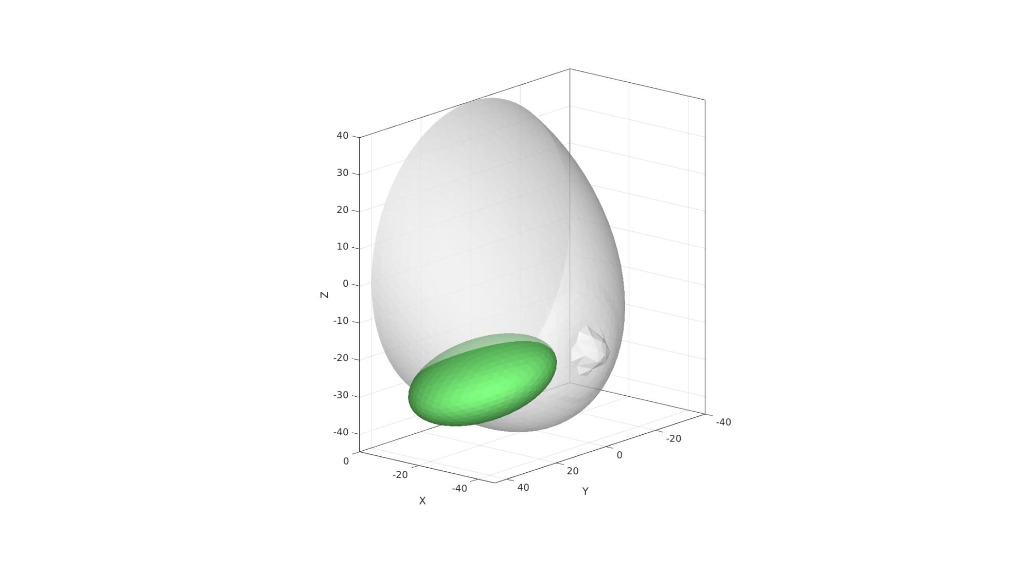
rCut=[10 20 20];
nRefineCut=nRefine;
[Fs,Vs]=geoSphere(nRefineCut,1);
Fs=fliplr(Fs);
R_cut1=euler2DCM([0 0 0.5*pi]);
R_cut2=euler2DCM([-0.5*pi -0.1*pi -0.2*pi]);
R_cut=R_cut1*R_cut2;
Vs=Vs.*rCut(ones(size(Vs,1),1),:);
Vs=Vs*R_cut;
T_cut=[-25 25 -25];
Vs=Vs+T_cut(ones(size(Vs,1),1),:);
cFigure; hold on;
gpatch(F,V,'w','none',0.5);
gpatch(Fs,Vs,'gw','none',1);

axisGeom; view([-140,16]);
camlight headlight;
drawnow;
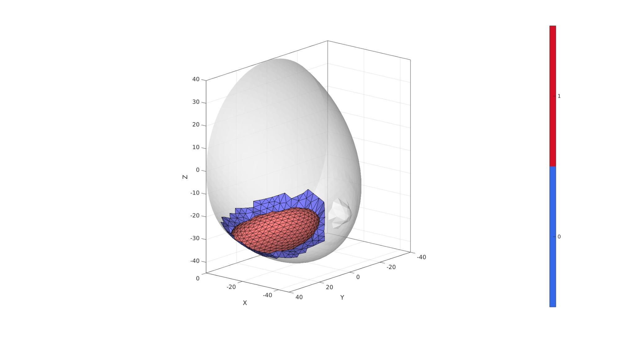
[regionLabel]=simplexImIntersect(Fs,Vs,[],V,pointSpacing/2);
logicCutVertices=~isnan(regionLabel);
logicCutFaces=any(logicCutVertices(F),2);
logicCutFaces=triSurfLogicSharpFix(F,logicCutFaces,3);
Eb=patchBoundary(F(logicCutFaces,:));
logicCutFaces=~logicCutFaces & ~any(ismember(F,Eb),2);
logicCutFaces=triSurfLogicSharpFix(F,logicCutFaces,3);

[regionLabel]=simplexImIntersect(F,V,[],Vs,pointSpacing/2);
logicCutVertices=(regionLabel==1);
logicCutFaces_s=any(logicCutVertices(Fs),2);
logicCutFaces_s=triSurfLogicSharpFix(Fs,logicCutFaces_s,3);

% Eb=patchBoundary(Fs(logicCutFaces_s,:));
% logicCutFaces_s=logicCutFaces_s & ~any(ismember(Fs,Eb),2);
% logicCutFaces_s=triSurfLogicSharpFix(Fs,logicCutFaces_s,3);

Fs=Fs(logicCutFaces_s,:);
[Fs,Vs]=patchCleanUnused(Fs,Vs);
Eb=patchBoundary(Fs); %Get boundary edges
indBoundary=edgeListToCurve(Eb); %Convert boundary edges to a curve list
indBoundary=indBoundary(1:end-1); %Trim off last point since it is equal to first on a closed loop
angleThreshold=pi*(120/180); %threshold for self triangulation
[Fs,Vs,indBoundaryTop]=triSurfSelfTriangulateBoundary(Fs,Vs,indBoundary,angleThreshold,1);

F=F(logicCutFaces,:);
C_skin_F=C_skin_F(logicCutFaces,:);
[F,V]=patchCleanUnused(F,V);
Eb=patchBoundary(F);
ind1=edgeListToCurve(Eb);
ind1=ind1(1:end-1);

Eb=patchBoundary(Fs);
ind2=edgeListToCurve(Eb);
ind2=ind2(1:end-1);

% Fs=Fs(~logicCutFaces_s,:);

[Fn,Vn]=regionTriMesh3D({V(ind1,:),Vs(ind2,:)},pointSpacing,0,'linear');
Fn=fliplr(Fn);
cFigure; hold on;
gpatch(F,V,'w','none',0.5);
gpatch(Fs,Vs,'rw','k',1);
gpatch(Fn,Vn,'bw','k',1);
axisGeom; view([-140,16]);
camlight headlight;
colormap gjet; icolorbar;
drawnow;
[FT,VT,CT]=joinElementSets({F,Fs,Fn},{V,Vs,Vn},{C_skin_F,(max(C_skin_F)+1)*ones(size(Fs,1),1),(max(C_skin_F)+2)*ones(size(Fn,1),1)});
[FT,VT]=mergeVertices(FT,VT);
indRim=unique(FT(CT==5,:));
logicFacesSmooth=any(ismember(FT,indRim),2);
indSmooth=FT(logicFacesSmooth,:);
indRigid=FT(~ismember(FT,indSmooth));
clear cParSmooth;
cParSmooth.n=25;
cParSmooth.Method='HC';
cParSmooth.RigidConstraints=indRigid;
[VT]=patchSmooth(FT,VT,[],cParSmooth);
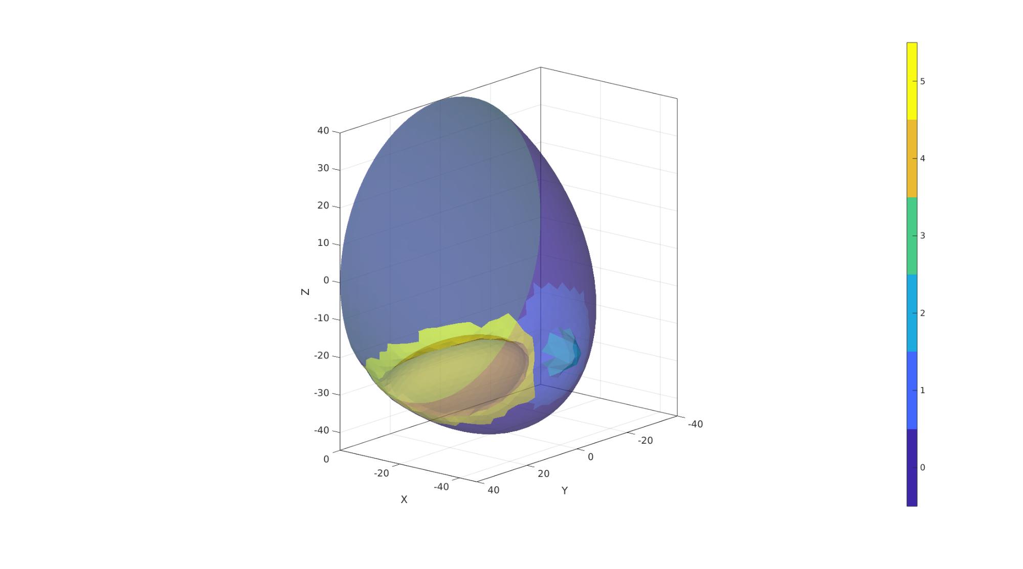
cFigure; hold on;
gpatch(FT,VT,CT,'k',1);
axisGeom; view([-140,16]);
camlight headlight;
colormap gjet; icolorbar;
drawnow;

V_regions=getInnerPoint(FT,VT);

[regionA]=tetVolMeanEst(FT,VT); %Volume for regular tets
inputStruct.stringOpt='-pq1.2AaY';
inputStruct.Faces=FT;
inputStruct.Nodes=VT;
inputStruct.holePoints=[];
inputStruct.faceBoundaryMarker=CT; %Face boundary markers
inputStruct.regionPoints=V_regions; %region points
inputStruct.regionA=regionA*ones(size(V_regions,1),1)*volumeFactor;

% Mesh model using tetrahedral elements using tetGen
[meshOutput]=runTetGen(inputStruct); %Run tetGen

% Access model element and patch data
Fb=meshOutput.facesBoundary;
Cb=meshOutput.boundaryMarker;
V=meshOutput.nodes;
CE=meshOutput.elementMaterialID;
E=meshOutput.elements;
%%%%%%%%%%%%%%%%%%%%%%%%%%%%%%%%%%%%%%%%%%%%%
--- TETGEN Tetrahedral meshing --- 29-May-2023 10:35:21

%%%%%%%%%%%%%%%%%%%%%%%%%%%%%%%%%%%%%%%%%%%%%
--- Writing SMESH file --- 29-May-2023 10:35:21
----> Adding node field
----> Adding facet field
----> Adding holes specification
----> Adding region specification
--- Done --- 29-May-2023 10:35:21
--- Running TetGen to mesh input boundary--- 29-May-2023 10:35:21
Opening /home/kevin/DATA/Code/matlab/GIBBON/data/temp/temp.smesh.
Delaunizing vertices...
Delaunay seconds:  0.007858
Creating surface mesh ...
Surface mesh seconds:  0.001577
Recovering boundaries...
Boundary recovery seconds:  0.003583
Removing exterior tetrahedra ...
Spreading region attributes.
Exterior tets removal seconds:  0.001359
Recovering Delaunayness...
Delaunay recovery seconds:  0.001545
Refining mesh...
  2765 insertions, added 2709 points, 69556 tetrahedra in queue.
Refinement seconds:  0.036278
Smoothing vertices...
Mesh smoothing seconds:  0.0655
Improving mesh...
Mesh improvement seconds:  0.002662

Writing /home/kevin/DATA/Code/matlab/GIBBON/data/temp/temp.1.node.
Writing /home/kevin/DATA/Code/matlab/GIBBON/data/temp/temp.1.ele.
Writing /home/kevin/DATA/Code/matlab/GIBBON/data/temp/temp.1.face.
Writing /home/kevin/DATA/Code/matlab/GIBBON/data/temp/temp.1.edge.

Output seconds:  0.010982
Total running seconds:  0.13147

Statistics:

  Input points: 2075
  Input facets: 4146
  Input segments: 6219
  Input holes: 0
  Input regions: 1

  Mesh points: 5088
  Mesh tetrahedra: 24772
  Mesh faces: 51617
  Mesh faces on exterior boundary: 4146
  Mesh faces on input facets: 4146
  Mesh edges on input segments: 6219
  Steiner points inside domain: 3013

--- Done --- 29-May-2023 10:35:21

%%%%%%%%%%%%%%%%%%%%%%%%%%%%%%%%%%%%%%%%%%%%%
--- Importing TetGen files --- 29-May-2023 10:35:21
--- Done --- 29-May-2023 10:35:21
cFigure; hold on;
hp=gpatch(Fb,V,Cb,'none',0.5);
axisGeom; view([-140,16]);
camlight headlight;
icolorbar;
drawnow;
Visualizing mesh using meshView, see also anim8
% meshView(meshOutput);
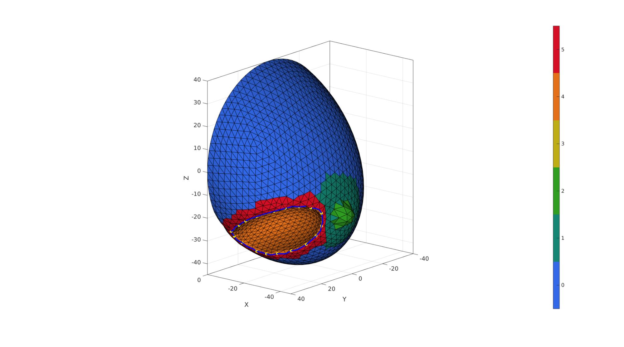
Eb=patchBoundary(Fb(Cb==4,:));
indRim=edgeListToCurve(Eb);
indRim=indRim(1:end-1);

nContract=18;
V_rim_resample=evenlySampleCurve(V(indRim,:),nContract,'linear',1);
[~,indMin]=minDist(V_rim_resample,V(indRim,:));
indPresribeStitch=indRim(indMin)';
V_stitch=V(indPresribeStitch,:);
cFigure; hold on;
gpatch(Fb,V,Cb,'k',1);
plotV(V(indRim,:),'b-','LineWidth',3);
plotV(V_stitch,'y.','MarkerSize',25);
axisGeom; view([-140,16]);
camlight headlight;
colormap gjet; icolorbar;
drawnow;
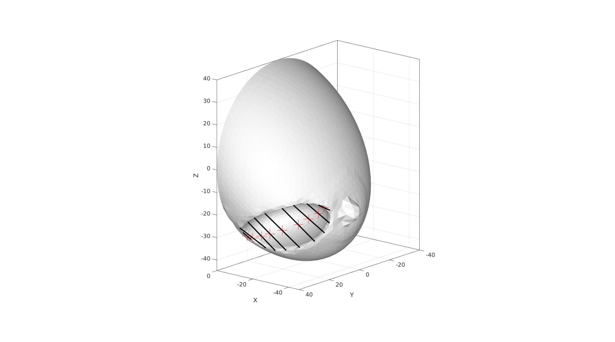
V_stitch_temp=V_stitch-T_cut(ones(size(V_stitch,1),1),:);
V_stitch_temp=V_stitch_temp*R_cut';
[~,indStart]=min((V_stitch_temp(:,2)));
if indStart>1
    V_stitch=[V_stitch(indStart:end,:); V_stitch(1:indStart-1,:)];
    indPresribeStitch=[indPresribeStitch(indStart:end); indPresribeStitch(1:indStart-1)];
end

indStitchOrigin=(1:round(nContract/2))';
indStitchEnd=nContract-(indStitchOrigin-1);
indStitchPair=[indStitchOrigin indStitchEnd];

V_stitchGoal=patchCentre(indStitchPair,V_stitch);

u1=V_stitchGoal-V_stitch(indStitchOrigin,:);
u2=V_stitchGoal-V_stitch(indStitchEnd,:);
u=[u1;u2];
cFigure; hold on;
gpatch(Fb,V,'w','none',1);
% plotV(V(indRim,:),'b-','LineWidth',3);
% plotV(V_stitch,'y.-','MarkerSize',25,'LineWidth',3);
plotV(V_stitchGoal,'r+','MarkerSize',25);
gpatch(indStitchPair,V_stitch,'none','k',1,3);
axisGeom; view([-140,16]);
camlight headlight;
drawnow;
Define boundary conditions
%Supported nodes
logicRigid=Cb==3;
Fr=Fb(logicRigid,:);
bcSupportList=unique(Fr(:));

bcPrescribeList1=indPresribeStitch(indStitchOrigin);
bcPrescribeList2=indPresribeStitch(indStitchEnd);
bcPrescribeList=[bcPrescribeList1(:); bcPrescribeList2(:);];
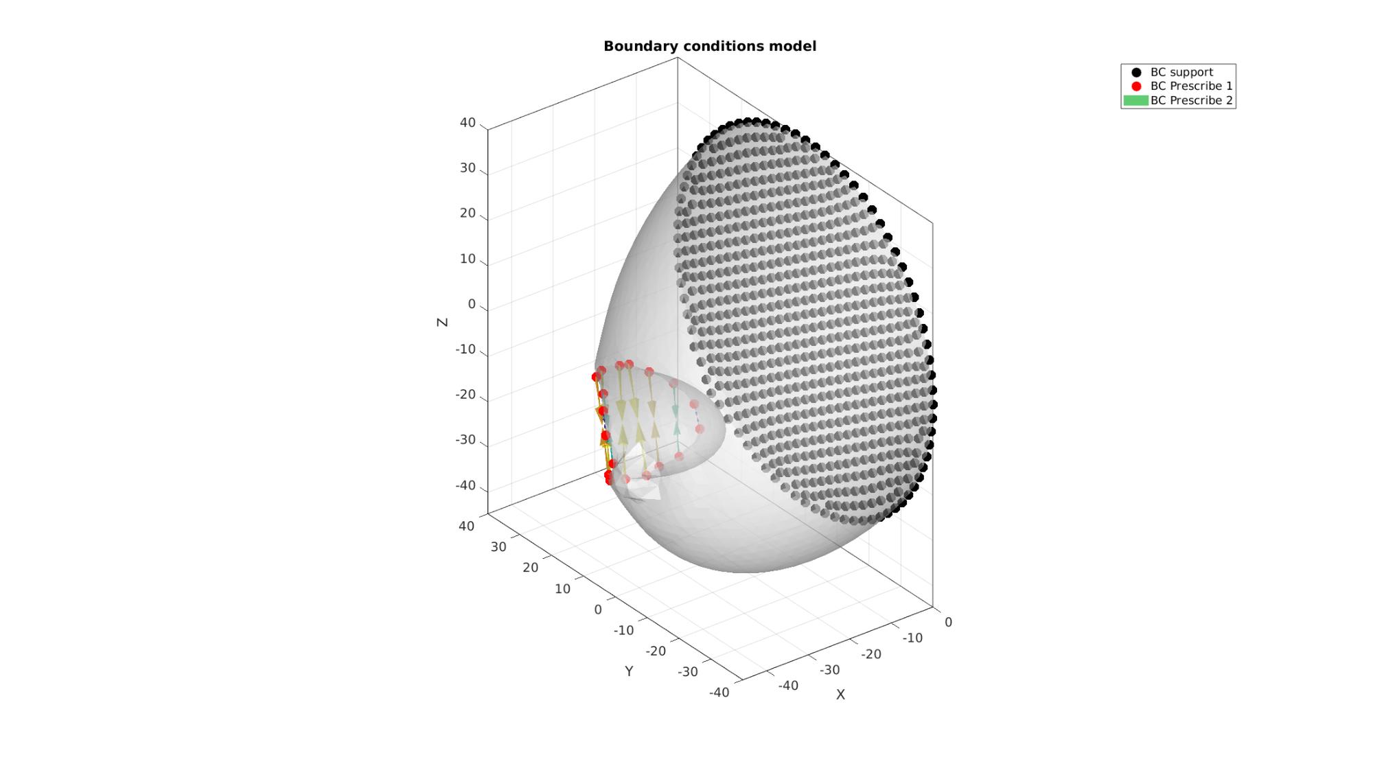
Visualize BC's
hf=cFigure;
title('Boundary conditions model','FontSize',fontSize);
xlabel('X','FontSize',fontSize); ylabel('Y','FontSize',fontSize); zlabel('Z','FontSize',fontSize);
hold on;

gpatch(Fb,V,'w','none',faceAlpha2);

hl2(1)=plotV(V(bcSupportList,:),'k.','MarkerSize',markerSize);
hl2(2)=plotV(V(bcPrescribeList,:),'r.','MarkerSize',markerSize);
hl2(3)=quiverVec(V(bcPrescribeList,:),u);
legend(hl2,{'BC support','BC Prescribe 1','BC Prescribe 2'});

axisGeom(gca,fontSize);
camlight headlight;
drawnow;
Defining the FEBio input structure
See also febioStructTemplate and febioStruct2xml and the FEBio user manual.
%Get a template with default settings
[febio_spec]=febioStructTemplate;

%febio_spec version
febio_spec.ATTR.version='4.0';

%Module section
febio_spec.Module.ATTR.type='solid';

%Control section
febio_spec.Control.analysis='STATIC';
febio_spec.Control.time_steps=numTimeSteps;
febio_spec.Control.step_size=1/numTimeSteps;
febio_spec.Control.solver.max_refs=max_refs;
febio_spec.Control.solver.qn_method.max_ups=max_ups;
febio_spec.Control.time_stepper.dtmin=dtmin;
febio_spec.Control.time_stepper.dtmax=dtmax;
febio_spec.Control.time_stepper.max_retries=max_retries;
febio_spec.Control.time_stepper.opt_iter=opt_iter;

%Material section
materialName1='Material1';
febio_spec.Material.material{1}.ATTR.name=materialName1;
febio_spec.Material.material{1}.ATTR.type='Ogden';
febio_spec.Material.material{1}.ATTR.id=1;
febio_spec.Material.material{1}.c1=c1_1;
febio_spec.Material.material{1}.m1=m1_1;
febio_spec.Material.material{1}.c2=c1_1;
febio_spec.Material.material{1}.m2=-m1_1;
febio_spec.Material.material{1}.k=k_1;

% Mesh section
% -> Nodes
febio_spec.Mesh.Nodes{1}.ATTR.name='All'; %The node set name
febio_spec.Mesh.Nodes{1}.node.ATTR.id=(1:size(V,1))'; %The node id's
febio_spec.Mesh.Nodes{1}.node.VAL=V; %The nodel coordinates

% -> Elements
partName1='Part1';
febio_spec.Mesh.Elements{1}.ATTR.name=partName1; %Name of this part
febio_spec.Mesh.Elements{1}.ATTR.type='tet4'; %Element type
febio_spec.Mesh.Elements{1}.elem.ATTR.id=(1:1:size(E,1))'; %Element id's
febio_spec.Mesh.Elements{1}.elem.VAL=E; %The element matrix

% -> NodeSets
nodeSetName1='bcSupportList';
febio_spec.Mesh.NodeSet{1}.ATTR.name=nodeSetName1;
febio_spec.Mesh.NodeSet{1}.VAL=mrow(bcSupportList);

nodeSetName2='bcPrescribeList';
febio_spec.Mesh.NodeSet{2}.ATTR.name=nodeSetName2;
febio_spec.Mesh.NodeSet{2}.VAL=mrow(bcPrescribeList);

%MeshDomains section
febio_spec.MeshDomains.SolidDomain{1}.ATTR.name=partName1;
febio_spec.MeshDomains.SolidDomain{1}.ATTR.mat=materialName1;

%MeshData secion
%-> Node data
dofs='xyz';
for q=1:1:3
    bcDataName=['nodal_disp_',dofs(q)];
    febio_spec.MeshData.NodeData{q}.ATTR.name=bcDataName;
    febio_spec.MeshData.NodeData{q}.ATTR.node_set=nodeSetName2;
    febio_spec.MeshData.NodeData{q}.ATTR.data_type='scalar';
    febio_spec.MeshData.NodeData{q}.node.ATTR.lid=(1:1:numel(bcPrescribeList))';
    febio_spec.MeshData.NodeData{q}.node.VAL=u(:,q);
end

%Boundary condition section
% -> Fix boundary conditions
febio_spec.Boundary.bc{1}.ATTR.name='zero_displacement_xyz';
febio_spec.Boundary.bc{1}.ATTR.type='zero displacement';
febio_spec.Boundary.bc{1}.ATTR.node_set=nodeSetName1;
febio_spec.Boundary.bc{1}.x_dof=1;
febio_spec.Boundary.bc{1}.y_dof=1;
febio_spec.Boundary.bc{1}.z_dof=1;

for q=1:1:3
    ind=numel(febio_spec.Boundary.bc)+1;
    bcDataName=['nodal_disp_',dofs(q)];
    febio_spec.Boundary.bc{ind}.ATTR.name=['prescibed_displacement_',dofs(q)];
    febio_spec.Boundary.bc{ind}.ATTR.type='prescribed displacement';
    febio_spec.Boundary.bc{ind}.ATTR.node_set=nodeSetName2;
    febio_spec.Boundary.bc{ind}.dof=dofs(q);
    febio_spec.Boundary.bc{ind}.value.ATTR.lc=1;
    febio_spec.Boundary.bc{ind}.value.ATTR.type='map';
    febio_spec.Boundary.bc{ind}.value.VAL=bcDataName;
    febio_spec.Boundary.bc{ind}.relative=0;
end

%LoadData section
% -> load_controller
febio_spec.LoadData.load_controller{1}.ATTR.name='LC_1';
febio_spec.LoadData.load_controller{1}.ATTR.id=1;
febio_spec.LoadData.load_controller{1}.ATTR.type='loadcurve';
febio_spec.LoadData.load_controller{1}.interpolate='LINEAR';
%febio_spec.LoadData.load_controller{1}.extend='CONSTANT';
febio_spec.LoadData.load_controller{1}.points.pt.VAL=[0 0; 1 1];

%Output section
% -> log file
febio_spec.Output.logfile.ATTR.file=febioLogFileName;
febio_spec.Output.logfile.node_data{1}.ATTR.file=febioLogFileName_disp;
febio_spec.Output.logfile.node_data{1}.ATTR.data='ux;uy;uz';
febio_spec.Output.logfile.node_data{1}.ATTR.delim=',';

% Plotfile section
febio_spec.Output.plotfile.compression=0;
Quick viewing of the FEBio input file structure
The febView function can be used to view the xml structure in a MATLAB figure window.
febView(febio_spec); %Viewing the febio file
Exporting the FEBio input file
Exporting the febio_spec structure to an FEBio input file is done using the febioStruct2xml function.
febioStruct2xml(febio_spec,febioFebFileName); %Exporting to file and domNode
Running the FEBio analysis
To run the analysis defined by the created FEBio input file the runMonitorFEBio function is used. The input for this function is a structure defining job settings e.g. the FEBio input file name. The optional output runFlag informs the user if the analysis was run succesfully.
febioAnalysis.run_filename=febioFebFileName; %The input file name
febioAnalysis.run_logname=febioLogFileName; %The name for the log file
febioAnalysis.disp_on=1; %Display information on the command window
febioAnalysis.disp_log_on=1; %Display convergence information in the command window
febioAnalysis.runMode=runMode;
febioAnalysis.t_check=0.25; %Time for checking log file (dont set too small)
febioAnalysis.maxtpi=1e99; %Max analysis time
febioAnalysis.maxLogCheckTime=10; %Max log file checking time

[runFlag]=runMonitorFEBio(febioAnalysis);%START FEBio NOW!!!!!!!!
%%%%%%%%%%%%%%%%%%%%%%%%%%%%%%%%%%%%%%%%%%%%%%%%%%%%%%%%%%%%%%%%%%%%%%%%%%%
-------->    RUNNING/MONITORING FEBIO JOB    <-------- 29-May-2023 10:35:24
FEBio path: /home/kevin/FEBioStudio/bin/febio4
# Attempt removal of existing log files                29-May-2023 10:35:24
 * Removal succesful                                   29-May-2023 10:35:24
# Attempt removal of existing .xplt files              29-May-2023 10:35:24
 * Removal succesful                                   29-May-2023 10:35:24
# Starting FEBio...                                    29-May-2023 10:35:24
  Max. total analysis time is: 1e+99 s
 * Waiting for log file creation                       29-May-2023 10:35:24
   Max. wait time: 10 s
 * Log file found.                                     29-May-2023 10:35:25
# Parsing log file...                                  29-May-2023 10:35:25
    number of iterations   : 3                         29-May-2023 10:35:25
    number of reformations : 3                         29-May-2023 10:35:25
------- converged at time : 0.0666667                  29-May-2023 10:35:25
    number of iterations   : 3                         29-May-2023 10:35:25
    number of reformations : 3                         29-May-2023 10:35:25
------- converged at time : 0.133333                   29-May-2023 10:35:25
    number of iterations   : 3                         29-May-2023 10:35:26
    number of reformations : 3                         29-May-2023 10:35:26
------- converged at time : 0.2                        29-May-2023 10:35:26
    number of iterations   : 3                         29-May-2023 10:35:26
    number of reformations : 3                         29-May-2023 10:35:26
------- converged at time : 0.266667                   29-May-2023 10:35:26
    number of iterations   : 3                         29-May-2023 10:35:27
    number of reformations : 3                         29-May-2023 10:35:27
------- converged at time : 0.333333                   29-May-2023 10:35:27
    number of iterations   : 3                         29-May-2023 10:35:27
    number of reformations : 3                         29-May-2023 10:35:27
------- converged at time : 0.4                        29-May-2023 10:35:27
    number of iterations   : 3                         29-May-2023 10:35:27
    number of reformations : 3                         29-May-2023 10:35:27
------- converged at time : 0.466667                   29-May-2023 10:35:27
    number of iterations   : 3                         29-May-2023 10:35:27
    number of reformations : 3                         29-May-2023 10:35:27
------- converged at time : 0.533333                   29-May-2023 10:35:27
    number of iterations   : 4                         29-May-2023 10:35:28
    number of reformations : 4                         29-May-2023 10:35:28
------- converged at time : 0.6                        29-May-2023 10:35:28
    number of iterations   : 4                         29-May-2023 10:35:28
    number of reformations : 4                         29-May-2023 10:35:28
------- converged at time : 0.666667                   29-May-2023 10:35:28
    number of iterations   : 11                        29-May-2023 10:35:30
    number of reformations : 11                        29-May-2023 10:35:30
------- converged at time : 0.711111                   29-May-2023 10:35:30
    number of iterations   : 5                         29-May-2023 10:35:31
    number of reformations : 5                         29-May-2023 10:35:31
------- converged at time : 0.753518                   29-May-2023 10:35:31
    number of iterations   : 4                         29-May-2023 10:35:32
    number of reformations : 4                         29-May-2023 10:35:32
------- converged at time : 0.800777                   29-May-2023 10:35:32
    number of iterations   : 4                         29-May-2023 10:35:32
    number of reformations : 4                         29-May-2023 10:35:32
------- converged at time : 0.851918                   29-May-2023 10:35:32
    number of iterations   : 4                         29-May-2023 10:35:32
    number of reformations : 4                         29-May-2023 10:35:32
------- converged at time : 0.906164                   29-May-2023 10:35:32
    number of iterations   : 4                         29-May-2023 10:35:32
    number of reformations : 4                         29-May-2023 10:35:32
------- converged at time : 0.962894                   29-May-2023 10:35:32
    number of iterations   : 4                         29-May-2023 10:35:33
    number of reformations : 4                         29-May-2023 10:35:33
------- converged at time : 1                          29-May-2023 10:35:33
 Elapsed time : 0:00:08                                29-May-2023 10:35:33
 N O R M A L   T E R M I N A T I O N
# Done                                                 29-May-2023 10:35:33
%%%%%%%%%%%%%%%%%%%%%%%%%%%%%%%%%%%%%%%%%%%%%%%%%%%%%%%%%%%%%%%%%%%%%%%%%%%
Import FEBio results
if runFlag==1 %i.e. a succesful run
    % Importing nodal displacements from a log file
    [time_mat, N_disp_mat,~]=importFEBio_logfile(fullfile(savePath,febioLogFileName_disp)); %Nodal displacements
    time_mat=[0; time_mat(:)]; %Time

    N_disp_mat=N_disp_mat(:,2:end,:);
    sizImport=size(N_disp_mat);
    sizImport(3)=sizImport(3)+1;
    N_disp_mat_n=zeros(sizImport);
    N_disp_mat_n(:,:,2:end)=N_disp_mat;
    N_disp_mat=N_disp_mat_n;
    DN=N_disp_mat(:,:,end);
    DN_magnitude=sqrt(sum(DN(:,3).^2,2));
    V_def=V+DN;
    V_DEF=N_disp_mat+repmat(V,[1 1 size(N_disp_mat,3)]);
    X_DEF=V_DEF(:,1,:);
    Y_DEF=V_DEF(:,2,:);
    Z_DEF=V_DEF(:,3,:);
    %     [CF]=vertexToFaceMeasure(Fb,DN_magnitude);
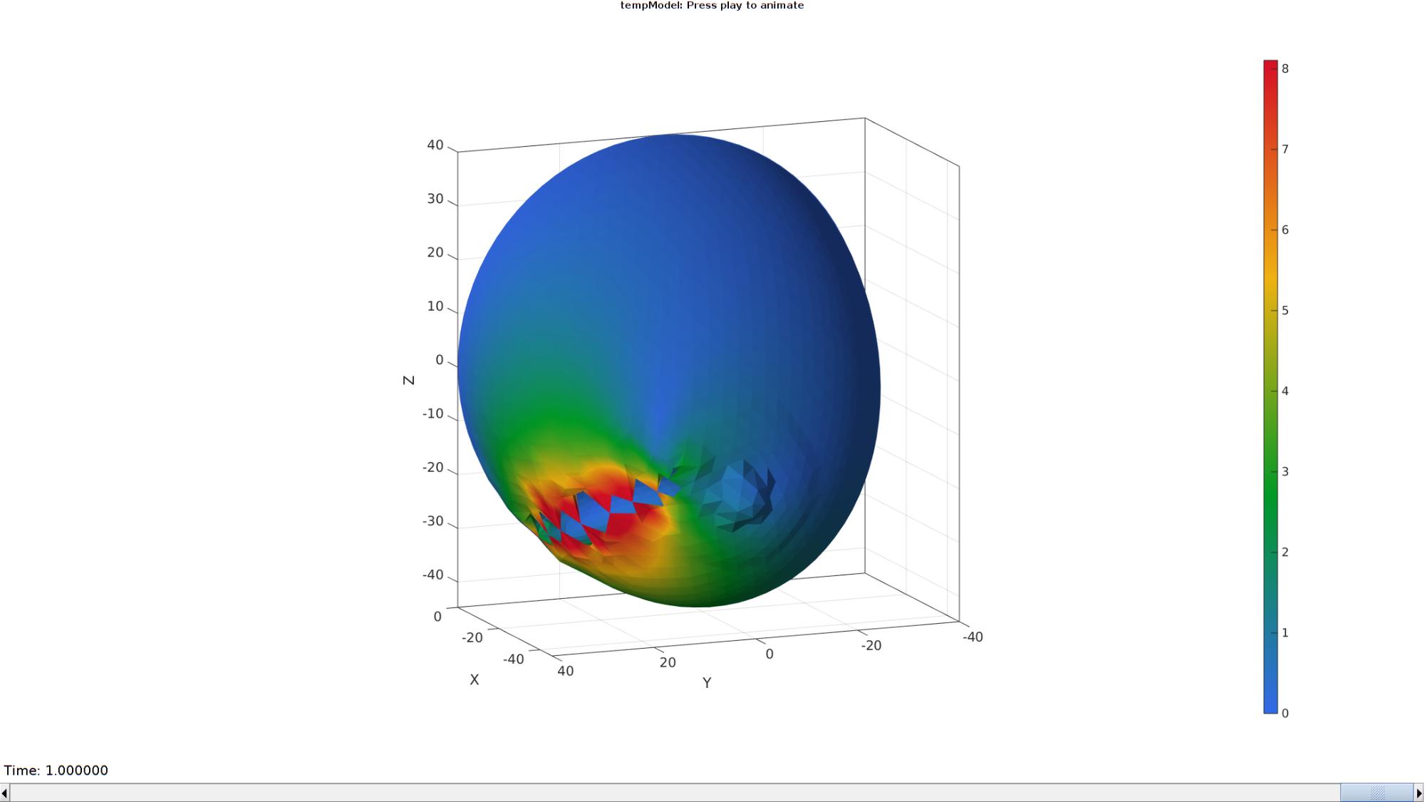
Plotting the simulated results using anim8 to visualize and animate deformations
    % Create basic view and store graphics handle to initiate animation
    hf=cFigure; %Open figure
    gtitle([febioFebFileNamePart,': Press play to animate']);
    hp1=gpatch(Fb,V_def,DN_magnitude,'none',1); %Add graphics object to animate
    hp1.FaceColor='Interp';

    %     gpatch(Fb,V,0.5*ones(1,3),'none',0.25); %A static graphics object

    axisGeom(gca,fontSize); view([-140,16]);
    colormap(gjet(250)); colorbar;
    caxis([0 max(DN_magnitude)]);
    axis([min(X_DEF(:)) max(X_DEF(:)) min(Y_DEF(:)) max(Y_DEF(:)) min(Z_DEF(:)) max(Z_DEF(:))]);
    camlight headlight;
    view([-112,12]);

    % Set up animation features
    animStruct.Time=time_mat; %The time vector
    for qt=1:1:size(N_disp_mat,3) %Loop over time increments
        DN=N_disp_mat(:,:,qt); %Current displacement
        DN_magnitude=sqrt(sum(DN.^2,2)); %Current displacement magnitude
        V_def=V+DN; %Current nodal coordinates
        %         [CF]=vertexToFaceMeasure(Fb,DN_magnitude); %Current color data to use

        %Set entries in animation structure
        animStruct.Handles{qt}=[hp1 hp1]; %Handles of objects to animate
        animStruct.Props{qt}={'Vertices','CData'}; %Properties of objects to animate
        animStruct.Set{qt}={V_def,DN_magnitude}; %Property values for to set in order to animate
    end
    anim8(hf,animStruct); %Initiate animation feature
    drawnow;
end

GIBBON www.gibboncode.org
Kevin Mattheus Moerman, [email protected]
GIBBON footer text
License: https://github.com/gibbonCode/GIBBON/blob/master/LICENSE
GIBBON: The Geometry and Image-based Bioengineering add-On. A toolbox for image segmentation, image-based modeling, meshing, and finite element analysis.
Copyright (C) 2006-2021 Kevin Mattheus Moerman and the GIBBON contributors
This program is free software: you can redistribute it and/or modify it under the terms of the GNU General Public License as published by the Free Software Foundation, either version 3 of the License, or (at your option) any later version.
This program is distributed in the hope that it will be useful, but WITHOUT ANY WARRANTY; without even the implied warranty of MERCHANTABILITY or FITNESS FOR A PARTICULAR PURPOSE. See the GNU General Public License for more details.
You should have received a copy of the GNU General Public License along with this program. If not, see http://www.gnu.org/licenses/.
GIBBON footer text
License: https://github.com/gibbonCode/GIBBON/blob/master/LICENSE
GIBBON: The Geometry and Image-based Bioengineering add-On. A toolbox for image segmentation, image-based modeling, meshing, and finite element analysis.
Copyright (C) 2006-2023 Kevin Mattheus Moerman and the GIBBON contributors
This program is free software: you can redistribute it and/or modify it under the terms of the GNU General Public License as published by the Free Software Foundation, either version 3 of the License, or (at your option) any later version.
This program is distributed in the hope that it will be useful, but WITHOUT ANY WARRANTY; without even the implied warranty of MERCHANTABILITY or FITNESS FOR A PARTICULAR PURPOSE. See the GNU General Public License for more details.
You should have received a copy of the GNU General Public License along with this program. If not, see http://www.gnu.org/licenses/.