DEMO_febio_0050_foot_insole_01
Below is a demonstration for:
- Building triangulated surface geometry for a foot
- Meshing the foot using tetrahedral elements
- Building surface model of an insole and meshing it with quads
- Extruding the surface to a thickened layer of hexahedral elements
- Defining the boundary conditions
- Coding the febio structure
- Running the model
- Importing and visualizing results
Contents
- Keywords
- Control parameters
- Import surface models
- Subdivide skin mesh and smooth
- Compute mesh derived parameters
- Reorient surfaces
- Cut skin surface
- Scale foot to desired size
- Close over top of skin
- Joining surface features
- Merge shared nodes
- Mesh foot with tetrahedral elements
- Build insole
- Joining node sets
- Define contact surfaces
- Define boundary conditions
- Set-up materials
- Convert list of materials to element id
- Defining the FEBio input structure
- Quick viewing of the FEBio input file structure
- Running the FEBio analysis
- Exporting the FEBio input file
- Run febio
- Set displacement magnitude in input file structure
- Export input file
- Run febio
- Importing rigid body reaction forces from a log file
- Use inter/extra-polation to guess displacement
- Import rigid body reaction forces
- Visualize force
- Plot animation
Keywords
- febio_spec version 4.0
- febio, FEBio
- shoe insole
- contact, sliding, friction
- tetrahedral elements, tet4
- hexahedral elements, hex8
- static, solid
- hyperelastic, Ogden
- displacement logfile
clear; close all; clc;
Plot settings
fontSize=15;
faceAlpha1=1;
faceAlpha2=0.3;
markerSize1=15;
markerSize2=10;
lineWidth=2;
Control parameters
% Path names
defaultFolder = fileparts(fileparts(mfilename('fullpath')));
savePath=fullfile(defaultFolder,'data','temp');
loadPathSurfaces=fullfile(defaultFolder,'data','STL','leg','post');

% Defining file names
febioFebFileNamePart='tempModel';
febioFebFileName=fullfile(savePath,[febioFebFileNamePart,'.feb']); %FEB file name
febioLogFileName=fullfile(savePath,[febioFebFileNamePart,'.txt']); %FEBio log file name
febioLogFileName_disp=[febioFebFileNamePart,'_disp_out.txt']; %Log file name for exporting displacement
febioLogFileName_force=[febioFebFileNamePart,'_force_out.txt']; %Log file name for exporting force
febioLogFileName_sed=[febioFebFileNamePart,'_energy_out.txt']; %Log file name for exporting strain energy density

% Surface model file names
fileNameBones=fullfile(loadPathSurfaces,'Foot_bulk.stl');
fileNameSkin=fullfile(loadPathSurfaces,'Skin_coarse.stl');

%Geometric parameters
soleOffsetOutward=3; %How much the insole protrudes outward from the foot
numSmoothIterations_sole_Z=15; %Number of smoothing iterations for the sole Z value
soleMinThickness=5; %Sole thickness
soleMaxThickness=10; %Sole thickness
volumeFactor=1; %Volume factor used in tetgen, larger means larger internal elements
footSize=251; %Foot size in mm size 6=241 mm, size 7=251 mm

% Material parameters
%-> Tissue (Ogden, uncoupled)
% Data source: Petre et al. 2013, Optimization of Nonlinear Hyperelastic
% Coefficients for Foot Tissues Using a Magnetic Resonance Imaging
% Deformation Experiment. https://dx.doi.org/10.1115%2F1.4023695
c1_1=0.02652; %Shear-modulus-like parameter in MPa
m1_1=17.71; %Material parameter setting degree of non-linearity
k_1=c1_1*100; %Bulk modulus

%-> Sole
%Sole material parameters (Ogden unconstrained, with m=2 i.e. Neo-Hookean)
E_youngs_min=0.05; %Shear-modulus-like parameter in MPa
E_youngs_max=0.1; %Shear-modulus-like parameter in MPa
numMaterialLevels=50; %Max number of materials to use
initialMaterialLevel=numMaterialLevels;
E_youngs_range=linspace(E_youngs_min,E_youngs_max,numMaterialLevels); %Shear-modulus-like parameter
nu=0.4;

testCase=1; % Change to test different sole cases, e.g. stiff, soft, spatially varying.
maxLevelColorbar_SED=0.0005;

% FEA control settings
numTimeSteps=10; %Number of time steps desired
max_refs=25; %Max reforms
max_ups=0; %Set to zero to use full-Newton iterations
opt_iter=10; %Optimum number of iterations
max_retries=8; %Maximum number of retires
dtmin=(1/numTimeSteps)/100; %Minimum time step size
dtmax=1/numTimeSteps; %Maximum time step size
symmetric_stiffness=0;
min_residual=1e-20;
runMode='external'; %'internal';

initialSoleSpacing=0.1;

%Boundary condition parameters
displacementMagnitude=-2.63; %Displacement applied to the bones
bodyWeight=65/2;% Body weight in Kg
forceBody=bodyWeight.*-9.81; %Force due to body weight
forceDifferenceToleranceFraction=0.05;
forceDifferenceTolerance=abs(forceBody.*forceDifferenceToleranceFraction);
optimizeForceOption=0; %set to 0 to turn off and use input displacement
maxProposedDisplacementDifference=1;

%Contact parameters
contactPenalty=10;
laugon=0;
minaug=1;
maxaug=10;
fric_coeff=0.25;
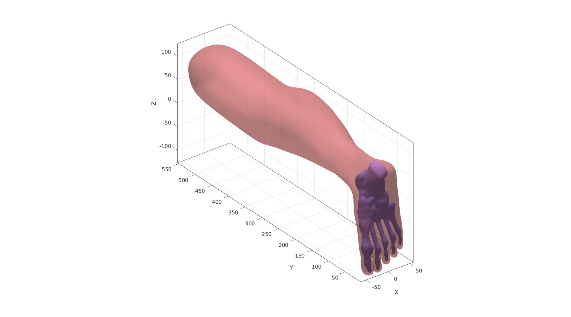
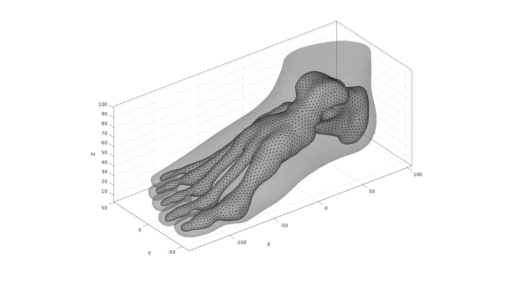
Import surface models
%Import STL file for the bones
[stlStruct] = import_STL(fileNameBones);
F1=stlStruct.solidFaces{1}; %Faces
V1=stlStruct.solidVertices{1}; %Vertices
[F1,V1]=mergeVertices(F1,V1); %Merge nodes

%Import STL file for the skin
[stlStruct] = import_STL(fileNameSkin);
F2=stlStruct.solidFaces{1}; %Faces
V2=stlStruct.solidVertices{1}; %Vertices
[F2,V2]=mergeVertices(F2,V2); %Merge nodes
V2=V2*100; %Scale
Subdivide skin mesh and smooth
% %Split elements once
% [F2,V2]=subtri(F2,V2,1);
%
% %Smooth
% clear cParSmooth;
% cParSmooth.n=5;
% cParSmooth.Method='HC';
% [V2]=patchSmooth(F2,V2,[],cParSmooth);
Visualize imported surfaces
cFigure; hold on;
gpatch(F1,V1,'bw','none',1);
gpatch(F2,V2,'rw','none',0.5);
camlight('headlight');
axisGeom(gca,fontSize);
drawnow;
Compute mesh derived parameters
Compute point spacings for the surfaces meshes. These are useful to relate other mesh sizes to.
pointSpacing1=mean(patchEdgeLengths(F1,V1));
pointSpacing2=mean(patchEdgeLengths(F2,V2));
pointSpacing=mean([pointSpacing1 pointSpacing2]);
pointSpacingSole=pointSpacing;
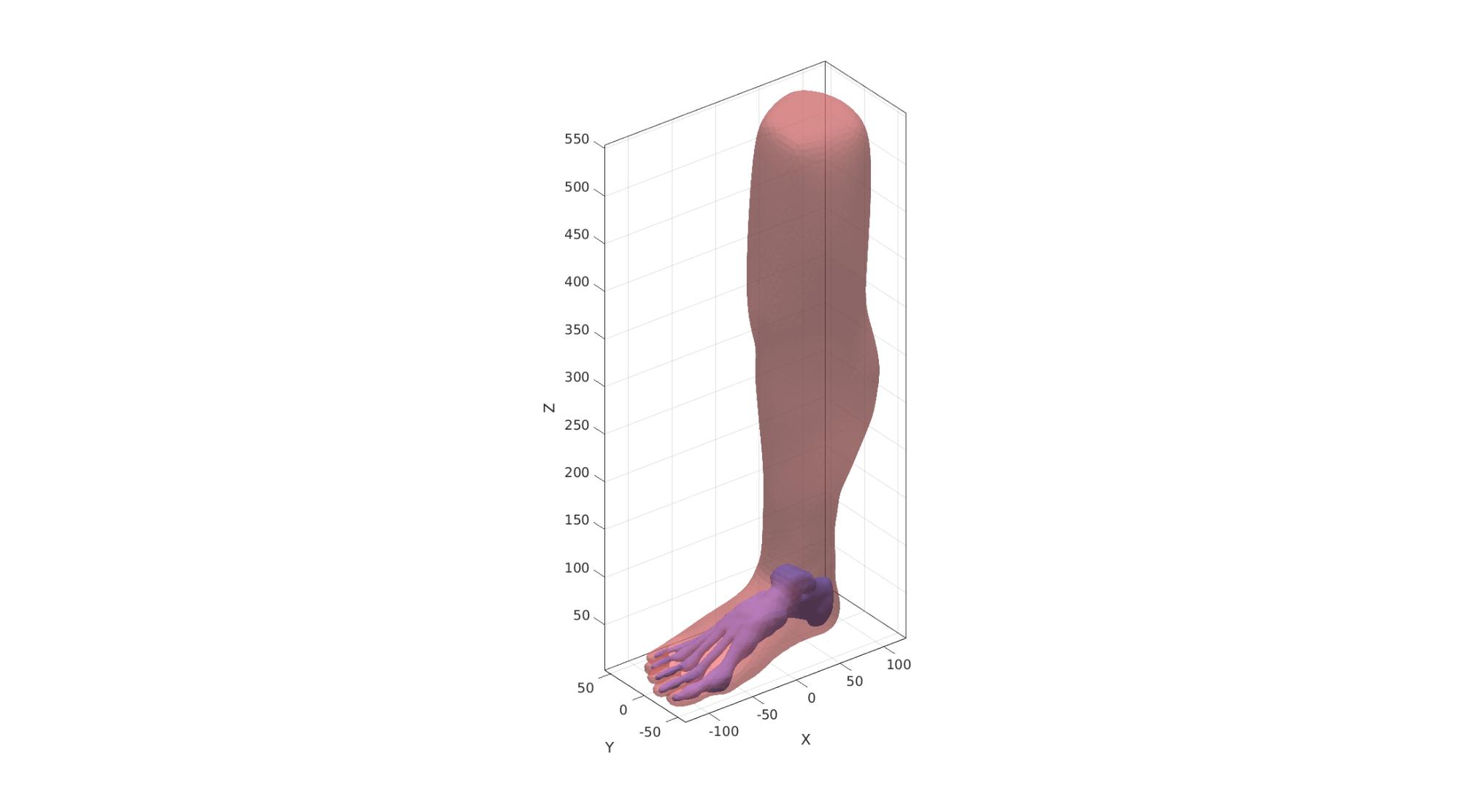
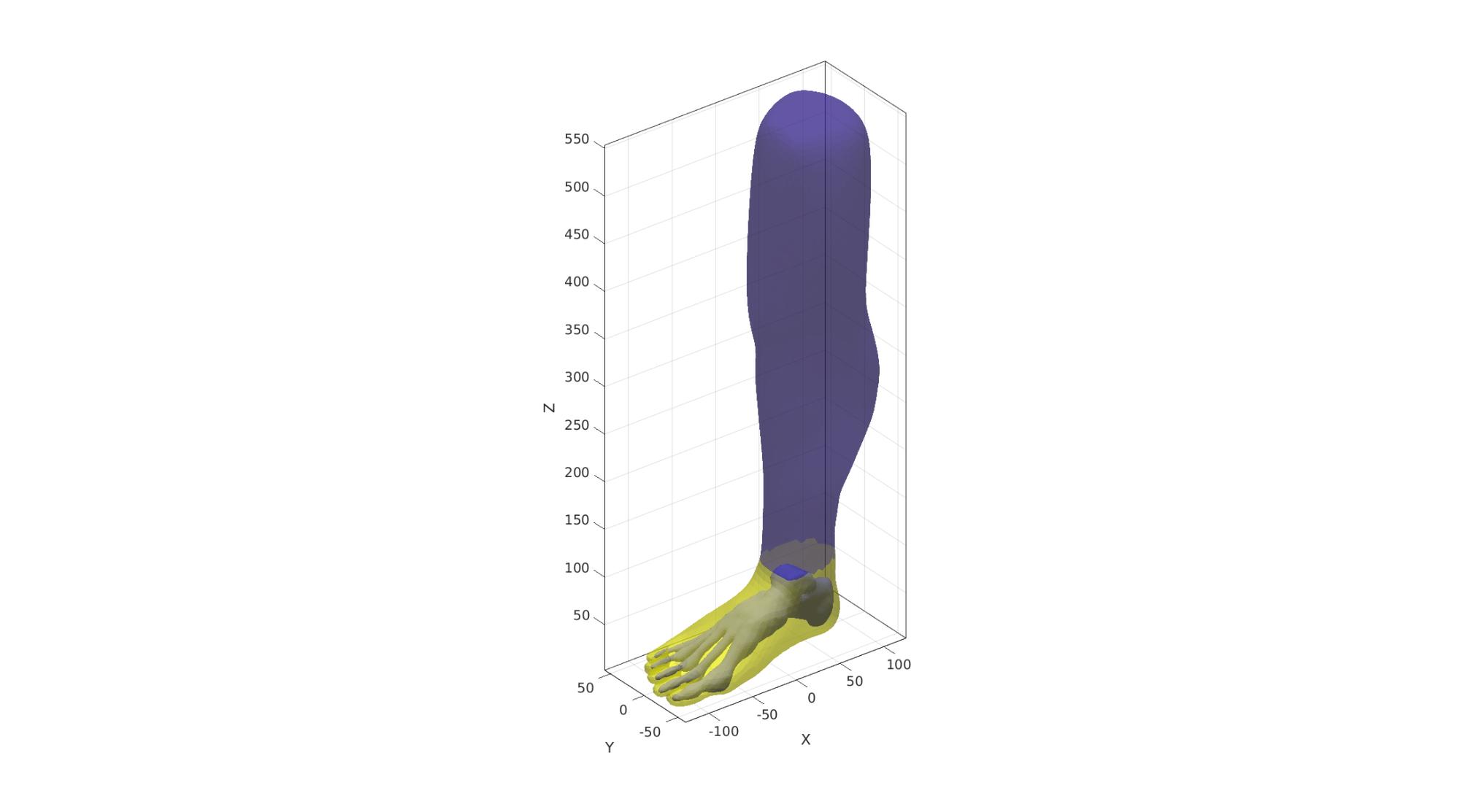
Reorient surfaces
Reorient so that the leg points up in a forward view with the toes pointing towards the viewer.
R=euler2DCM([-0.5*pi 0 -0.5*pi]);
V1=V1*R;
V2=V2*R;
Visualize reoriented surfaces
cFigure; hold on;
gpatch(F1,V1,'bw','none',1);
gpatch(F2,V2,'rw','none',0.5);
camlight('headlight');
axisGeom(gca,fontSize);
drawnow;
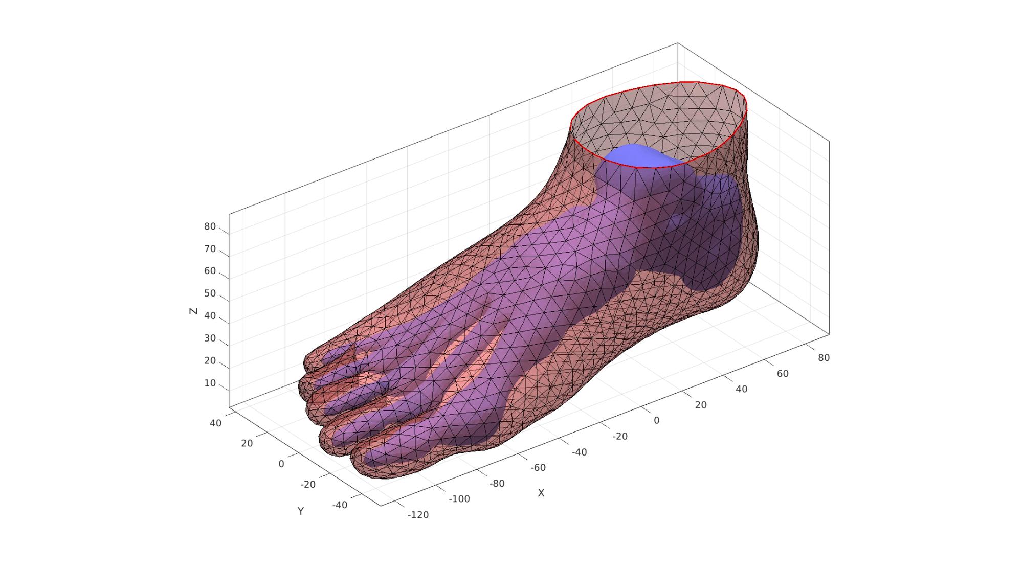
Cut skin surface
The skin surface is cut such that it stops where the bones of the ankle end in the z direction.
%Create a logic for cutting away faces
max_Z1=max(V1(:,3))+2*pointSpacing; %Max Z-level used for cutting
logicVertices=V2(:,3)<max_Z1; %Logic for the points below this level
logicFaces=all(logicVertices(F2),2); %Logic for the faces
logicFaces=triSurfLogicSharpFix(F2,logicFaces,3); %Altered logic so it is smoother
Visualize
cFigure; hold on;
gpatch(F1,V1,'bw','none',1);
gpatch(F2,V2,logicFaces,'none',0.5);
camlight('headlight');
axisGeom(gca,fontSize);
drawnow;
Cut away faces using logic
F2=F2(logicFaces,:); %The faces to keep
[F2,V2]=patchCleanUnused(F2,V2); %Remove unused points

%Attempt to self triangulate potentially jagged edge
Eb=patchBoundary(F2); %Get boundary edges
indBoundary=edgeListToCurve(Eb); %Convert boundary edges to a curve list
indBoundary=indBoundary(1:end-1); %Trim off last point since it is equal to first on a closed loop
angleThreshold=pi*(120/180); %threshold for self triangulation
[F2,V2,indBoundaryTop]=triSurfSelfTriangulateBoundary(F2,V2,indBoundary,angleThreshold,1);

%Force boundary to have the max Z level chosen
V2(indBoundaryTop,3)=max_Z1;
Visualize
cFigure; hold on;
gpatch(F1,V1,'bw','none',1);
gpatch(F2,V2,'rw','k',0.5);
plotV(V2(indBoundaryTop,:),'r-','LineWidth',lineWidth);
camlight('headlight');
axisGeom(gca,fontSize);
drawnow;
Scale foot to desired size
currentFootSize=abs(max(V2(:,1))-min(V2(:,1)));
V2=V2./currentFootSize; %Scale to unit foot
V2=V2.*footSize; %Scale to desired foot size
V1=V1./currentFootSize; %Scale to unit foot
V1=V1.*footSize; %Scale to desired foot size
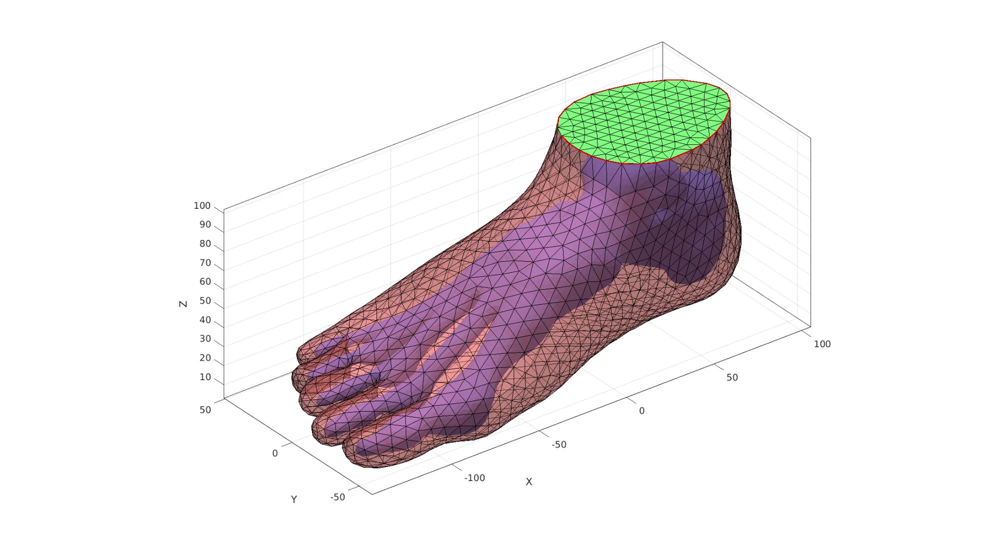
Close over top of skin
The top boundary curve of the cut surface is filled with triangles. This is a 2D method. The z-coordinate is added after.
[F2t,V2t]=regionTriMesh2D({V2(indBoundaryTop,[1 2])},pointSpacing2,0,0);
V2t(:,3)=mean(V2(indBoundaryTop,3)); %Add/set z-level
Visualize
cFigure; hold on;
gpatch(F1,V1,'bw','none',1);
gpatch(F2,V2,'rw','k',0.5);
gpatch(F2t,V2t,'gw','k',1);
plotV(V2(indBoundaryTop,:),'r-','LineWidth',lineWidth);
camlight('headlight');
axisGeom(gca,fontSize);
drawnow;
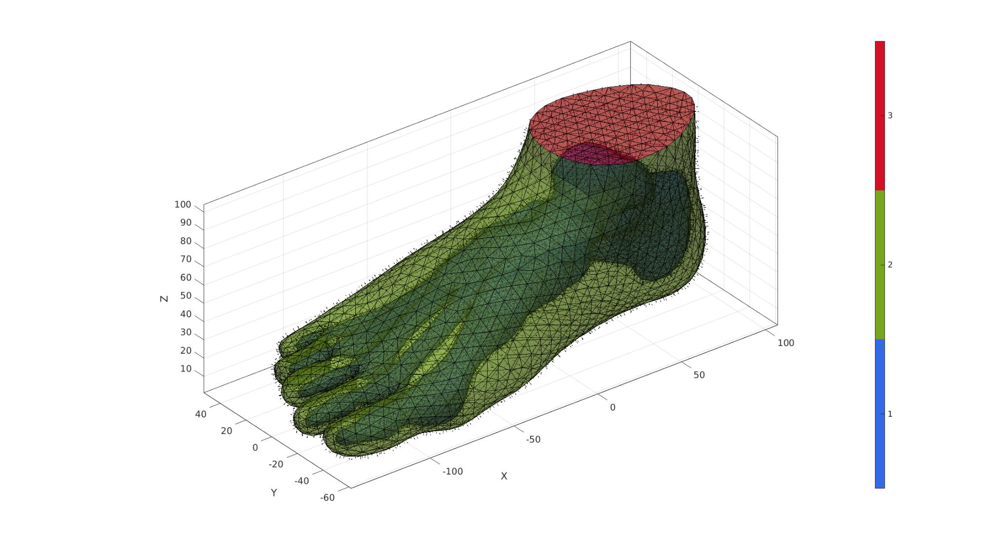
Joining surface features
Add all surface sets together in joint list of faces, vertices
[FT,VT,CT]=joinElementSets({F1,F2,F2t},{V1,V2,V2t});
Merge shared nodes
The join operation only adds the sets together. Nodes with the same coordinates are not seen as the same yet and need to be merged.
[FT,VT]=mergeVertices(FT,VT); %Merge nodes
Visualize
cFigure; hold on;
gpatch(FT,VT,CT,'k',0.5);
patchNormPlot(FT,VT);
camlight('headlight');
axisGeom(gca,fontSize);
colormap gjet; icolorbar;
drawnow;
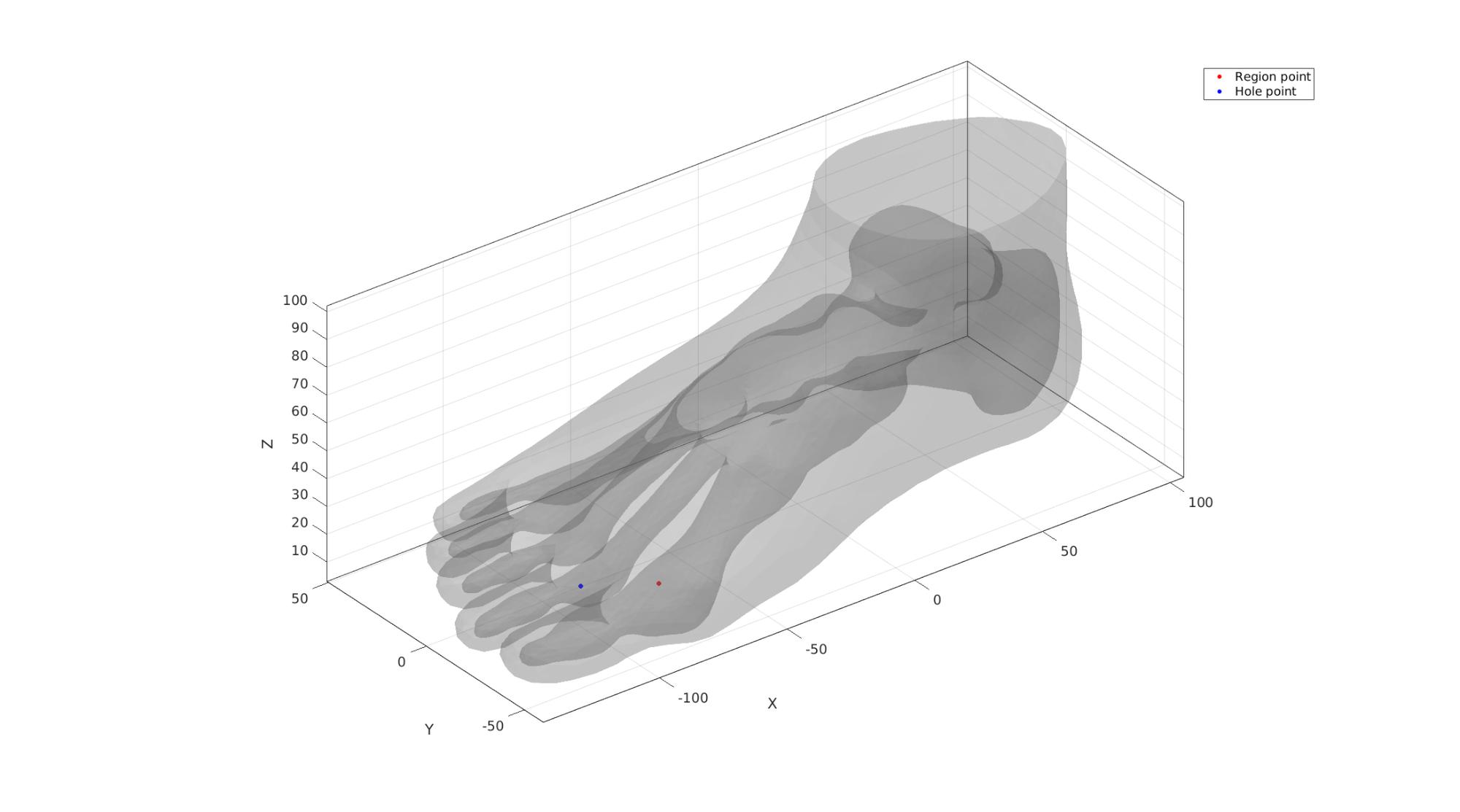
Mesh foot with tetrahedral elements
Tet meshing is based on tetgen. TetGen requires a interior points for regions to be meshed, as well as intertior points for holes.
Define region points
[V_region]=getInnerPoint({FT(CT==2 | CT==3,:),FT(CT==1,:)},{VT,VT});
[V_hole]=getInnerPoint(FT(CT==1,:),VT);
Visualize interior points
cFigure; hold on;
gpatch(FT,VT,'kw','none',0.2);
hp1=plotV(V_region,'r.','markerSize',markerSize1);
hp2=plotV(V_hole,'b.','markerSize',markerSize1);
legend([hp1 hp2],{'Region point','Hole point'});
camlight('headlight');
axisGeom(gca,fontSize);
drawnow;
Mesh using tetgen
inputStruct.stringOpt='-pq1.2AaY'; %TetGen option string
inputStruct.Faces=FT; %The faces
inputStruct.Nodes=VT; %The vertices
inputStruct.holePoints=V_hole; %The hole interior points
inputStruct.faceBoundaryMarker=CT; %Face boundary markers
inputStruct.regionPoints=V_region; %The region interior points
inputStruct.regionA=tetVolMeanEst(F2,V2)*volumeFactor; %Volume for regular tets
Mesh model using tetrahedral elements using tetGen
[meshOutput]=runTetGen(inputStruct); %Run tetGen
%%%%%%%%%%%%%%%%%%%%%%%%%%%%%%%%%%%%%%%%%%%%%
--- TETGEN Tetrahedral meshing --- 27-Apr-2023 16:18:02

%%%%%%%%%%%%%%%%%%%%%%%%%%%%%%%%%%%%%%%%%%%%%
--- Writing SMESH file --- 27-Apr-2023 16:18:02
----> Adding node field
----> Adding facet field
----> Adding holes specification
----> Adding region specification
--- Done --- 27-Apr-2023 16:18:02
--- Running TetGen to mesh input boundary--- 27-Apr-2023 16:18:02
Opening /mnt/data/MATLAB/GIBBON/data/temp/temp.smesh.
Delaunizing vertices...
Delaunay seconds:  0.031735
Creating surface mesh ...
Surface mesh seconds:  0.012355
Recovering boundaries...
Boundary recovery seconds:  0.025781
Removing exterior tetrahedra ...
Spreading region attributes.
Exterior tets removal seconds:  0.01477
Recovering Delaunayness...
Delaunay recovery seconds:  0.011781
Refining mesh...
  8715 insertions, added 4033 points, 82895 tetrahedra in queue.
  2902 insertions, added 229 points, 0 tetrahedra in queue.
Refinement seconds:  0.189777
Smoothing vertices...
Mesh smoothing seconds:  0.233285
Improving mesh...
Mesh improvement seconds:  0.010192

Writing /mnt/data/MATLAB/GIBBON/data/temp/temp.1.node.
Writing /mnt/data/MATLAB/GIBBON/data/temp/temp.1.ele.
Writing /mnt/data/MATLAB/GIBBON/data/temp/temp.1.face.
Writing /mnt/data/MATLAB/GIBBON/data/temp/temp.1.edge.

Output seconds:  0.122931
Total running seconds:  0.65311

Statistics:

  Input points: 6538
  Input facets: 13068
  Input segments: 19602
  Input holes: 1
  Input regions: 1

  Mesh points: 10942
  Mesh tetrahedra: 47679
  Mesh faces: 101892
  Mesh faces on exterior boundary: 13068
  Mesh faces on input facets: 13068
  Mesh edges on input segments: 19602
  Steiner points inside domain: 4404

--- Done --- 27-Apr-2023 16:18:03

%%%%%%%%%%%%%%%%%%%%%%%%%%%%%%%%%%%%%%%%%%%%%
--- Importing TetGen files --- 27-Apr-2023 16:18:03
--- Done --- 27-Apr-2023 16:18:03
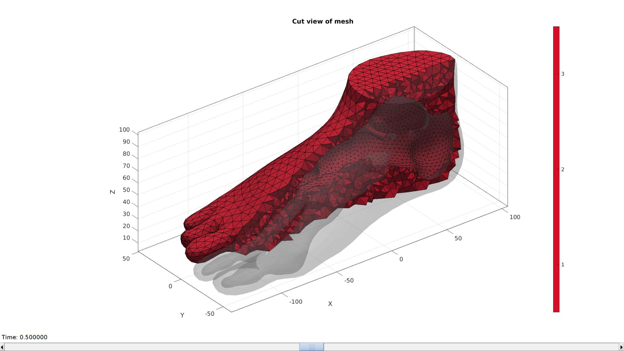
Access model element and patch data
Fb_foot=meshOutput.facesBoundary; %Boundary faces of the foot
Cb_foot=meshOutput.boundaryMarker; %Boundary marker/color data for the foot
V_foot=meshOutput.nodes; %The vertices/nodes
E_foot=meshOutput.elements; %The tet4 elements
Visualizing mesh using meshView, see also anim8
meshView(meshOutput);
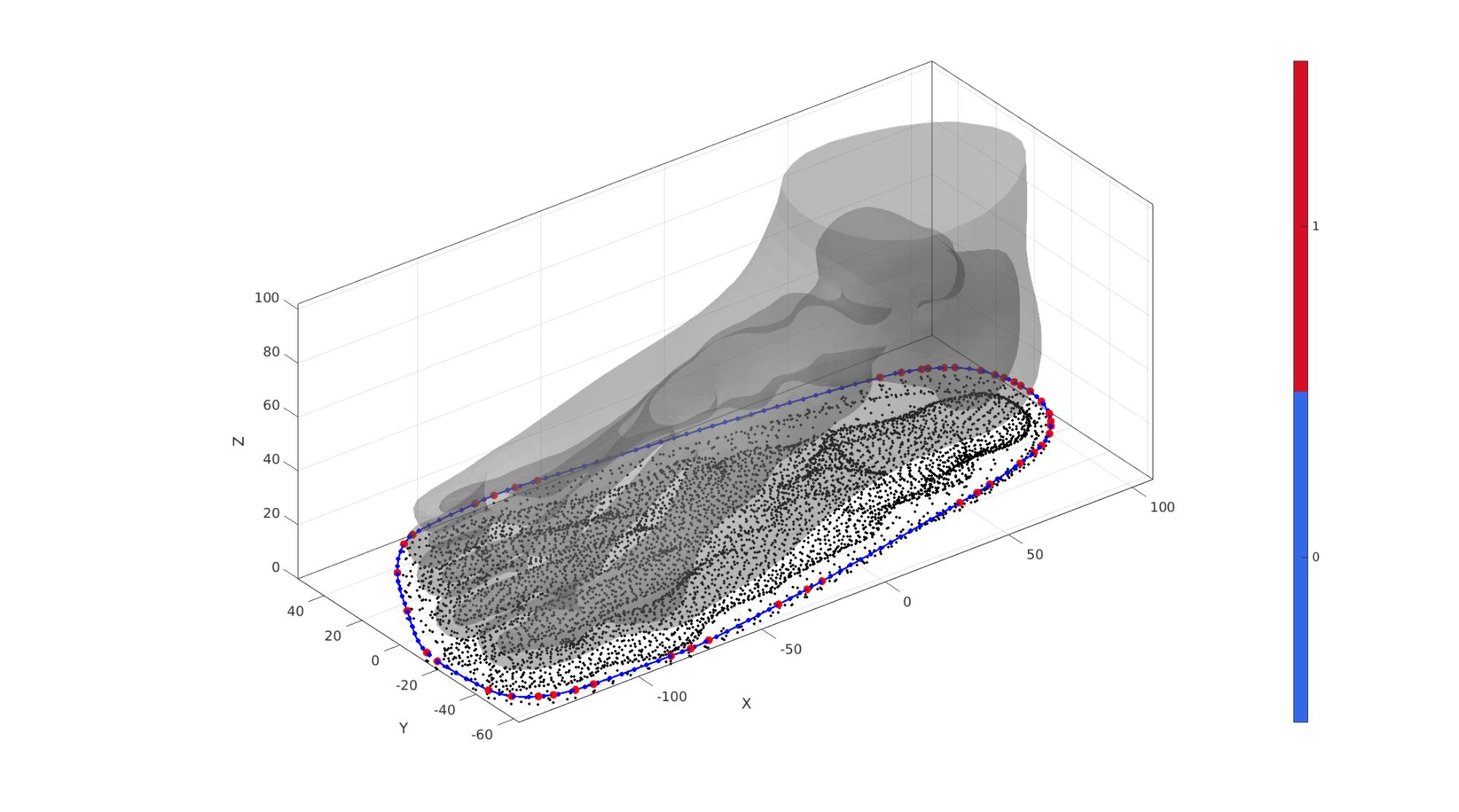
Build insole
The insole is created by taking the 2D convex hull of the foot (ignoring the z-direction). Next this convex hull is resampled and filled with triangular elements. The z-coordinates are then based on the nearest foot nodes. The z-coordinate data is next smoothed to create a smooth surface. This surface is next thickened to form hexahedral elements.
Create sole boundary curve in 2D
% Offset surface outward to thicken so sole is enlarged outward
[~,~,Nv]=patchNormal(FT,VT);
VT_sole=VT+soleOffsetOutward.*Nv;

P=VT_sole(:,[1 2]); %Point set flattened to 2D
DT=delaunayTriangulation(P); %Delaunay triangulation of 2D set
VD=DT.Points; %Delaunay point set
VD(:,3)=min(VT(:,3)); %Set z-coord to minimum for now
indChull=DT.convexHull; %Ordered point list for conhex hull
indChull=indChull(1:end-1); %Trim away last (=start) point to avoid double
V_chull=VD(indChull,:); %Vertices for convex hull
D=max(pathLength(V_chull)); %Get length of sole curve for resampling
numResample=ceil(D./pointSpacingSole);
V_sole_curve=evenlySampleCurve(V_chull,numResample,'pchip',1);
Visualize
cFigure; hold on;
gpatch(FT,VT,'kw','none',0.25);
plotV(P,'k.','MarkerSize',markerSize2);
plotV(V_chull,'r.','MarkerSize',markerSize1*2);
plotV(V_sole_curve,'b.-','MarkerSize',markerSize1,'LineWidth',lineWidth);
camlight('headlight');
axisGeom(gca,fontSize);
colormap gjet; icolorbar;
drawnow;
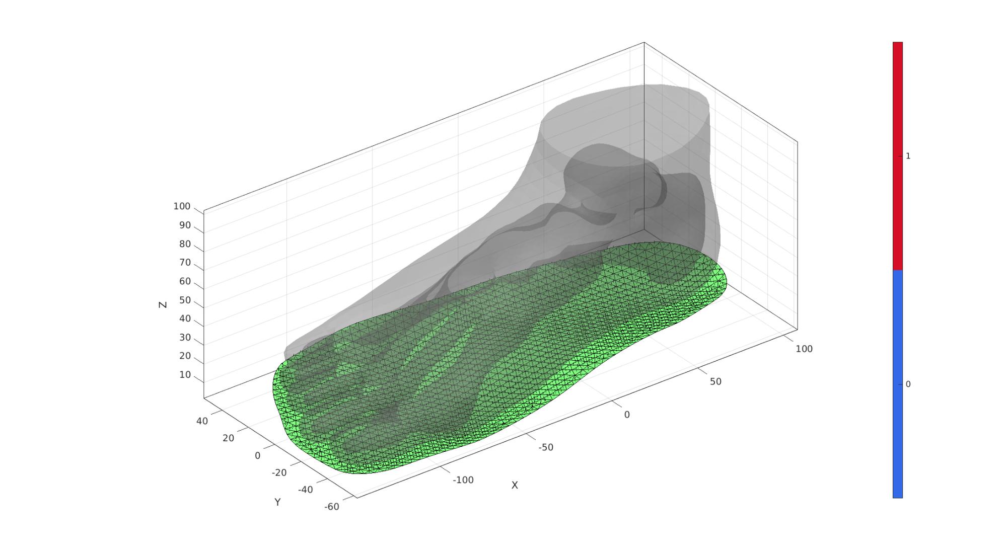
Build sole top surface
[F_sole_top,V_sole_top]=regionTriMesh2D({V_sole_curve(:,[1 2])},pointSpacingSole,0,0);
V_sole_top(:,3)=mean(V_sole_curve(:,3));

Eb=patchBoundary(F_sole_top);
indBoundary=unique(Eb(:));

%Get z-coordinate
[~,indMin]=minDist(V_sole_top,VT);
V_sole_top(:,3)=VT(indMin,3);

%Free smoothing of boundary
clear cParSmooth;
cParSmooth.n=numSmoothIterations_sole_Z;
cParSmooth.Method='LAP';
[p]=patchSmooth(Eb,V_sole_top,[],cParSmooth);
V_sole_top(indBoundary,3)=p(indBoundary,3);

% Constrained general smoothing
cParSmooth.n=numSmoothIterations_sole_Z;
cParSmooth.Method='LAP';
cParSmooth.RigidConstraints=indBoundary;
[V_sole_top(:,3)]=patchSmooth(F_sole_top,V_sole_top(:,3),[],cParSmooth);

%Shift a small amount to there is no initial contact
[~,indMin]=minDist(V_sole_top,VT);
dz=VT(indMin,3)-V_sole_top(:,3);
V_sole_top(:,3)=V_sole_top(:,3)-abs(min(dz));

V_sole_top(:,3)=V_sole_top(:,3)-initialSoleSpacing;
Visualize
cFigure; hold on;
gpatch(FT,VT,'kw','none',0.25);
gpatch(F_sole_top,V_sole_top,'gw','k',1);
patchNormPlot(F_sole_top,V_sole_top);
camlight('headlight');
axisGeom(gca,fontSize);
colormap gjet; icolorbar;
drawnow;
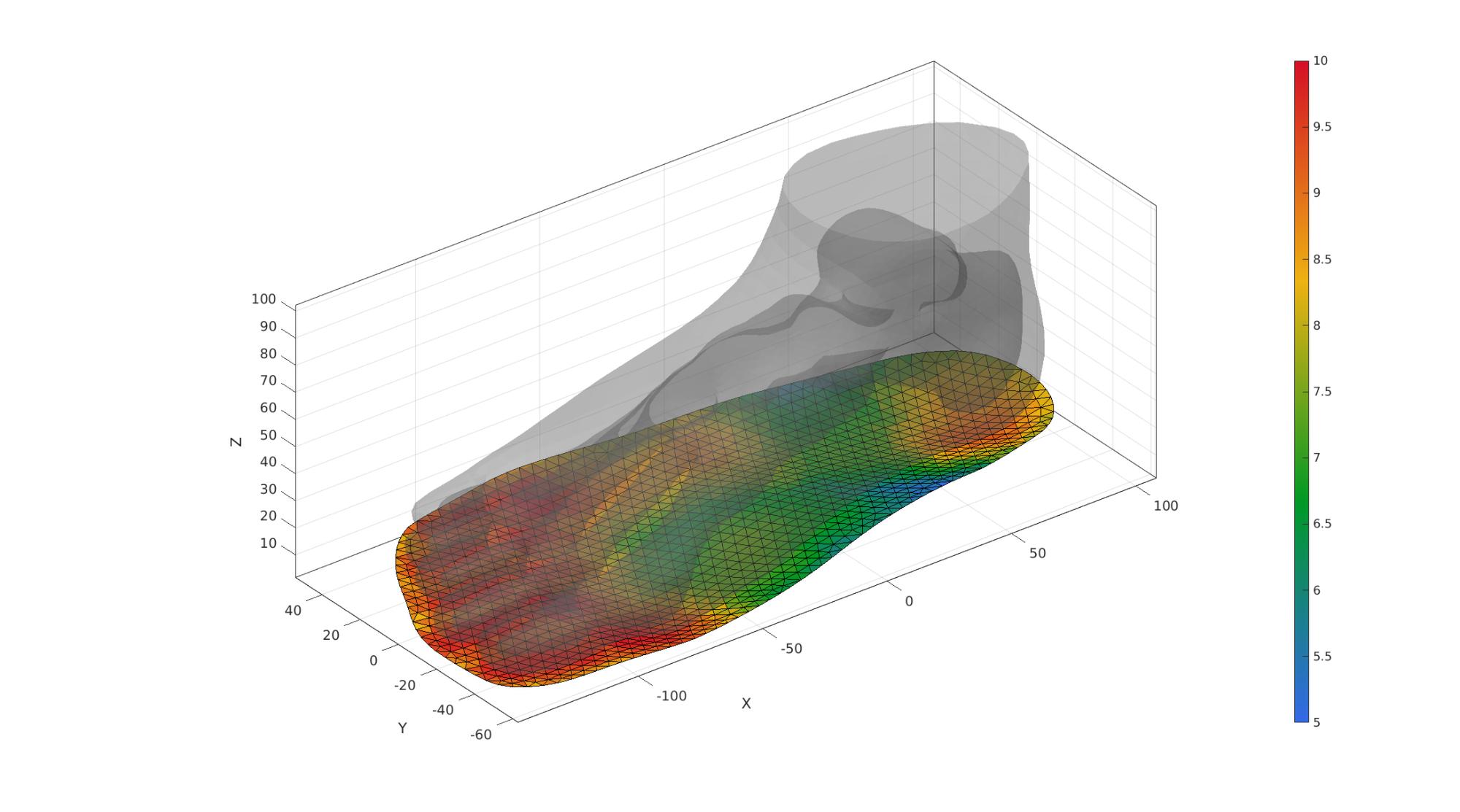
indBone=unique(Fb_foot(Cb_foot==1,:)); %Node numbers foot
D=minDist(V_sole_top,V_foot(indBone,:));
D=D-min(D(:));
D=D./max(D(:));
D=1-D;
spatVarThickness=(D*(soleMaxThickness-soleMinThickness))+soleMinThickness;
cFigure; hold on;
gpatch(FT,VT,'kw','none',0.25);
gpatch(F_sole_top,V_sole_top,spatVarThickness,'k',1);

camlight('headlight');
axisGeom(gca,fontSize);
colormap gjet; colorbar;
drawnow;
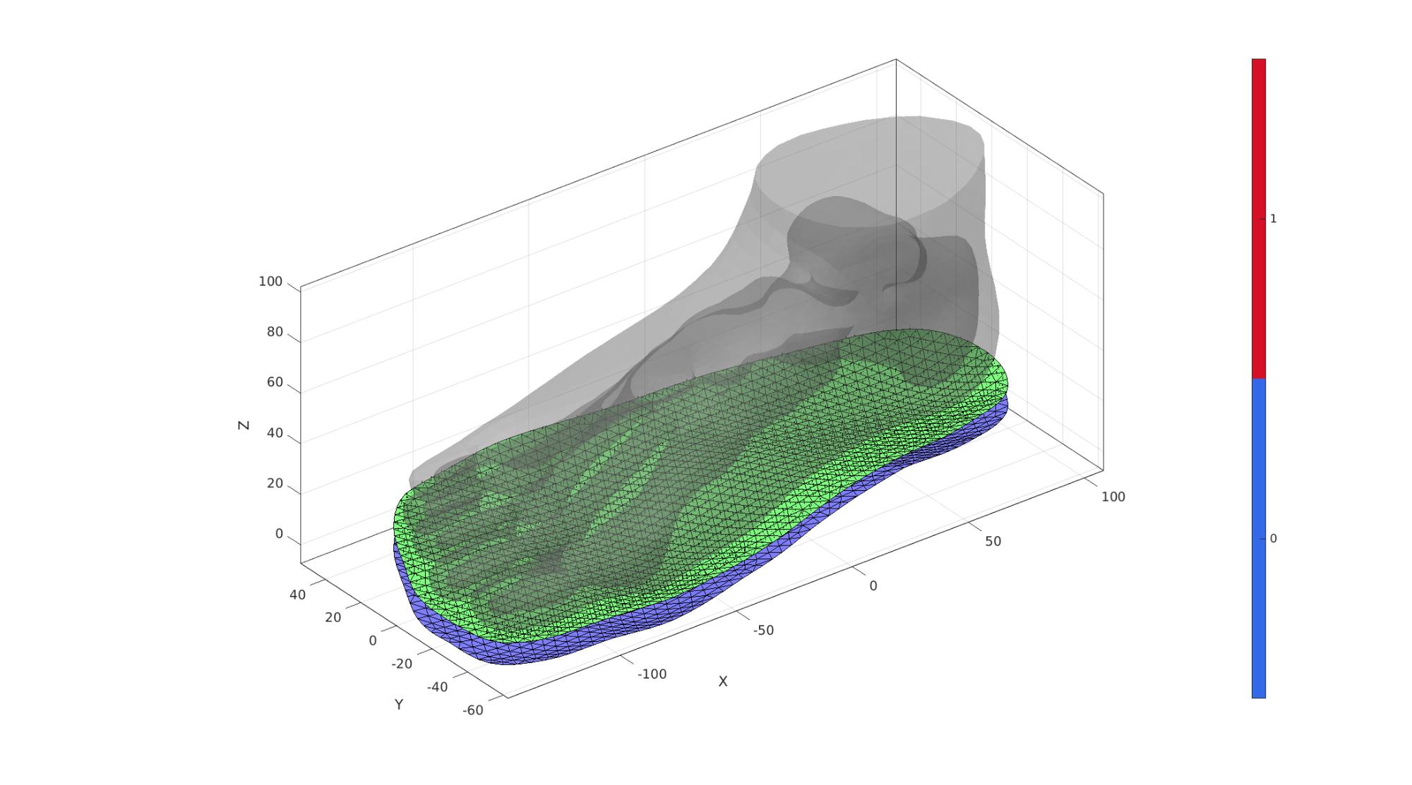
Create bottom surface of sole
dirSet=[0 0 -1];
numElementsSoleThickness=ceil(soleMaxThickness./pointSpacingSole);
[E_sole,V_sole,F_sole_top,F_sole_bottom]=patchThick(fliplr(F_sole_top),V_sole_top,dirSet,spatVarThickness,numElementsSoleThickness);
F_sole_top=fliplr(F_sole_top);

% Use element2patch to get patch data
F_E_sole=element2patch(E_sole,[],'penta6');
% indBoundaryFaces=tesBoundary(F_E_sole,V_sole);
% Fb_sole=F_E_sole(indBoundaryFaces,:);
cFigure; hold on;
gpatch(FT,VT,'kw','none',0.25);
gpatch(F_sole_top,V_sole,'gw','k',1);
gpatch(F_sole_bottom,V_sole,'bw','k',1);
patchNormPlot(F_sole_top,V_sole);
camlight('headlight');
axisGeom(gca,fontSize);
colormap gjet; icolorbar;
drawnow;
Visualize
cFigure; hold on;
title('Hexahedral mesh');
gpatch(FT,VT,'kw','none',0.25);
gpatch(F_E_sole,V_sole,'bw','k',1);
% patchNormPlot(Fb_sole,V_sole);
axisGeom;
camlight headlight;
drawnow;
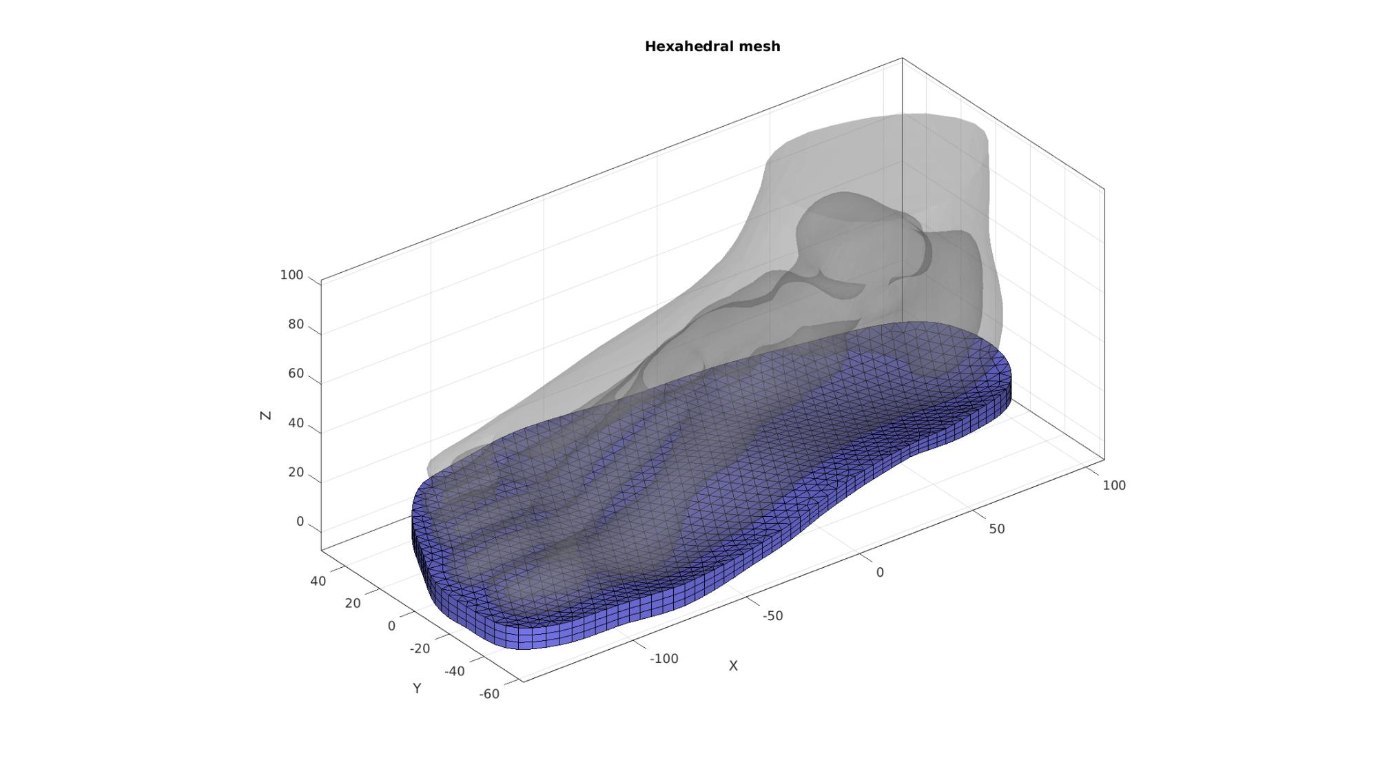
Joining node sets
V=[V_foot;V_sole;]; %Combined node sets
E_sole=E_sole+size(V_foot,1); %Fixed element indices
F_sole_top=F_sole_top+size(V_foot,1); %Fixed element indices
F_sole_bottom=F_sole_bottom+size(V_foot,1); %Fixed indices
F_E_sole=element2patch(E_sole,[],'penta6');
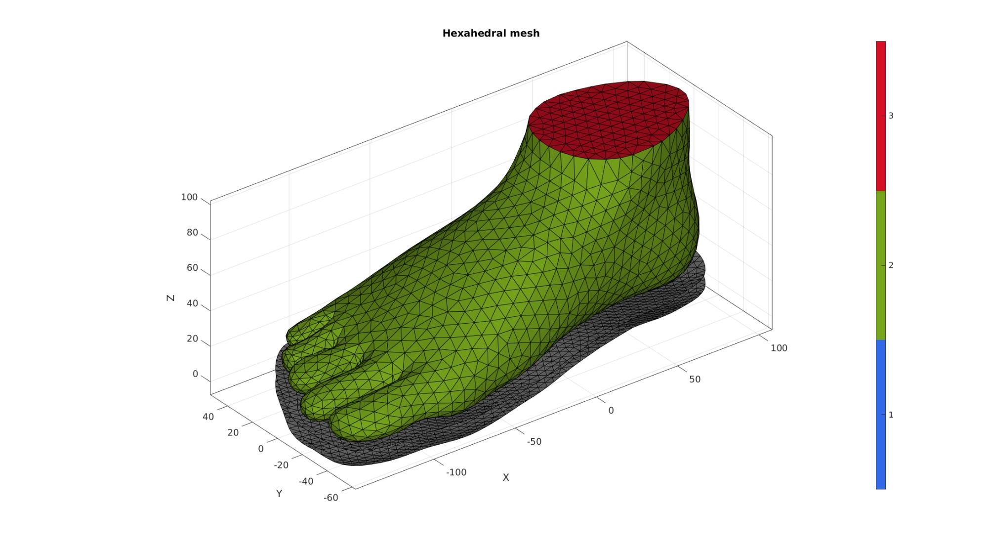
Visualize
cFigure; hold on;
title('Hexahedral mesh');
gpatch(Fb_foot,V,Cb_foot,'k',1);
gpatch(F_sole_top,V,'kw','k',1);
gpatch(F_sole_bottom,V,'kw','k',1);
% patchNormPlot(FEs,V);
colormap gjet; icolorbar;
axisGeom;
camlight headlight;
drawnow;
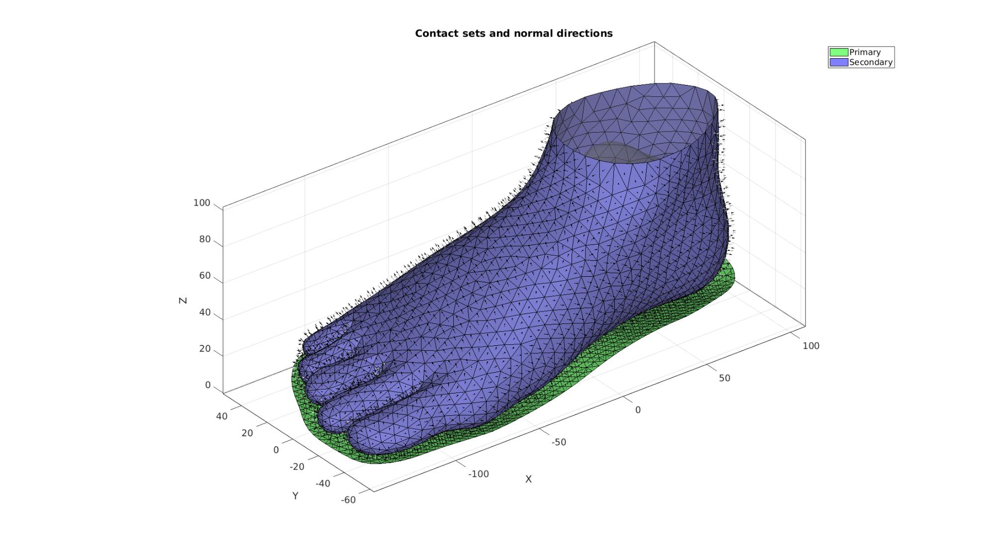
Define contact surfaces
% The rigid primary surface of the sphere
F_contact_primary=F_sole_top;

% The deformable secondary surface of the slab
F_contact_secondary=fliplr(Fb_foot(Cb_foot==2,:));
Visualize contact surfaces
cFigure; hold on;
title('Contact sets and normal directions','FontSize',fontSize);

gpatch(Fb_foot,V,'kw','none',faceAlpha2);
% gpatch(Fb_sole,V,'kw','none',faceAlpha2);

hl(1)=gpatch(F_contact_primary,V,'gw','k',1);
patchNormPlot(F_contact_primary,V);
hl(2)=gpatch(F_contact_secondary,V,'bw','k',1);
patchNormPlot(F_contact_secondary,V);

legend(hl,{'Primary','Secondary'});

axisGeom(gca,fontSize);
camlight headlight;
drawnow;
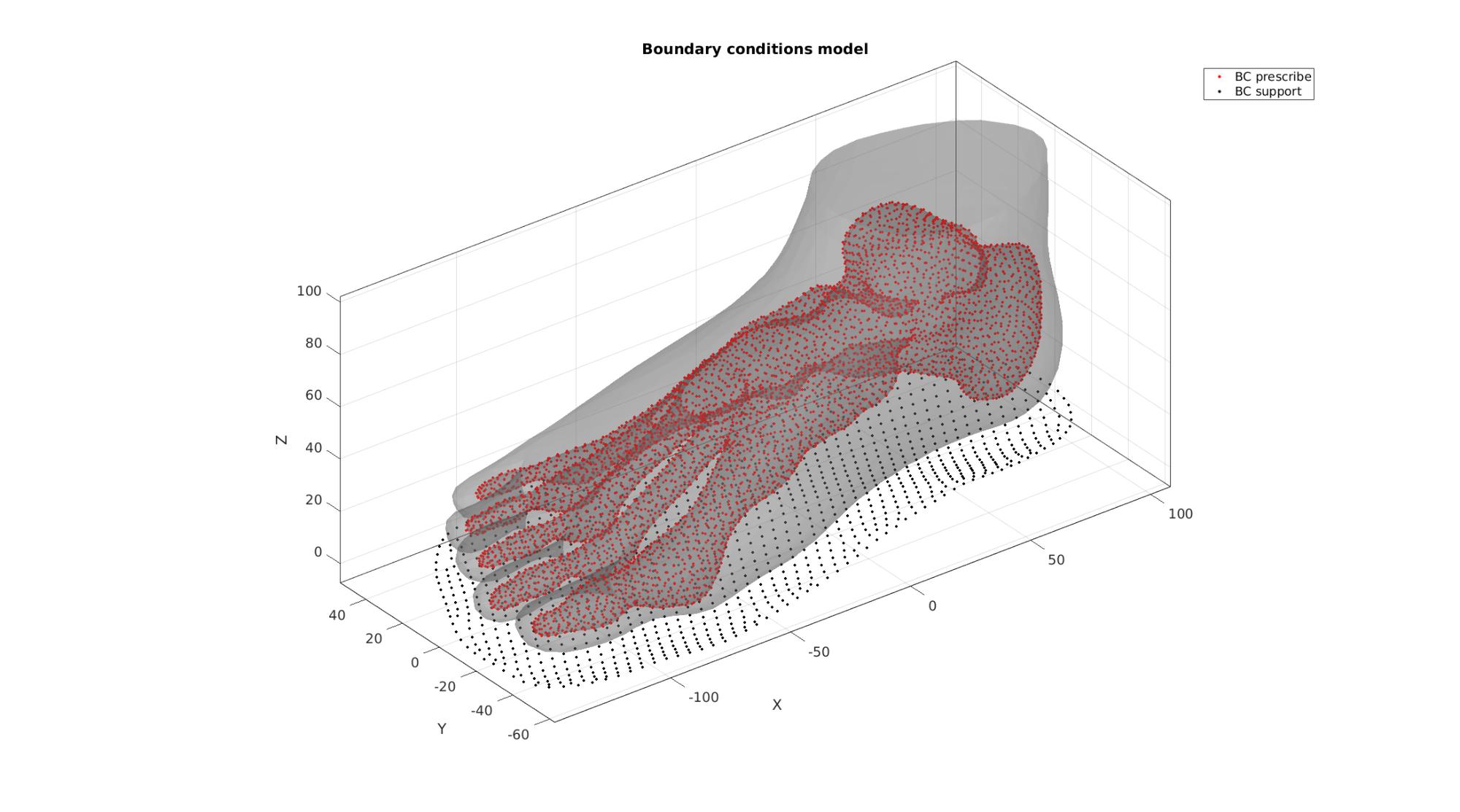
Define boundary conditions
%Supported nodes
bcSupportList=unique(F_sole_bottom);

%Prescribed displacement nodes
bcPrescribeList=unique(Fb_foot(Cb_foot==1,:));
Visualize BC's
hf=cFigure; hold on;
title('Boundary conditions model','FontSize',fontSize);
gpatch(Fb_foot,V,'kw','none',faceAlpha2);

hl2(1)=plotV(V(bcPrescribeList,:),'r.','MarkerSize',markerSize2);
hl2(2)=plotV(V(bcSupportList,:),'k.','MarkerSize',markerSize2);
legend(hl2,{'BC prescribe','BC support'});
axisGeom(gca,fontSize);
camlight headlight;
drawnow;
Visualize rigid body bone surface elements
F_bone=Fb_foot(Cb_foot==1,:);

center_of_mass_bone=mean(V(bcPrescribeList,:),1);

cFigure; hold on;
% title('Boundary conditions model','FontSize',fontSize);
gpatch(Fb_foot,V,'kw','none',faceAlpha2);
gpatch(F_bone,V,'w','k',1);
axisGeom(gca,fontSize);
camlight headlight;
drawnow;
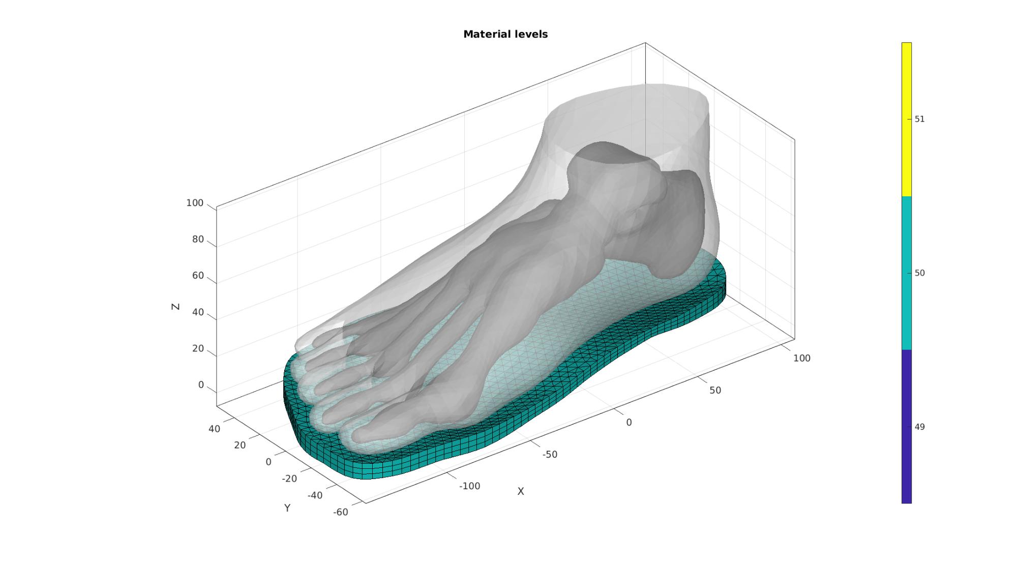
Set-up materials
switch testCase
    case 0 %Spatially varying based on bone distance
        VE=patchCentre(E_sole,V); %Element centres
        V_vulnerable=VT(bcPrescribeList,:);
        W=minDist(VE,V_vulnerable); %Distance to bone points
        W=W-min(W(:));
        W=W./max(W(:));
        W=W.*(E_youngs_max-E_youngs_min);
        W=W+E_youngs_min;
        E_youngs_desired=W;
    case 1 %
        E_youngs_desired=E_youngs_max*ones(size(E_sole,1),1);
    case 2
        E_youngs_desired=(E_youngs_max+E_youngs_min)/2*ones(size(E_sole,1),1);
    case 3
        E_youngs_desired=E_youngs_min*ones(size(E_sole,1),1);
end

%Snap to nearest available materials
[~,elementMaterialID]=minDist(E_youngs_desired(:),E_youngs_range(:));
Visualize material levels
%Use element2patch to get patch and color data
[F_E_sole,C_F_E_sole]=element2patch(E_sole,elementMaterialID,'penta6');

hf=cFigure; hold on;
title('Material levels','FontSize',fontSize);
gpatch(Fb_foot(Cb_foot==1,:),V,'kw','none',1);
gpatch(Fb_foot(Cb_foot~=1,:),V,'w','none',0.5);

for q=1:1:numel(F_E_sole)
    gpatch(F_E_sole{q},V,C_F_E_sole{q},'k',1);
end
axisGeom(gca,fontSize);
camlight headlight;
colormap parula;
icolorbar;
%caxis([0 maxLevelColorbar_SED]);
drawnow;
Convert list of materials to element id
%Sorting elements according to material label
[elementMaterialID,indSortElements]=sort(elementMaterialID);
E_sole=E_sole(indSortElements,:);

%Removing unused materials
[indUsed,ind1,ind2]=unique(elementMaterialID(:));
elementMaterialID=ind2;
E_youngs_set=E_youngs_range(indUsed);

numMaterials=numel(indUsed);

E_youngs_elem=E_youngs_set(elementMaterialID);
Defining the FEBio input structure
See also febioStructTemplate and febioStruct2xml and the FEBio user manual.
%Get a template with default settings
[febio_spec]=febioStructTemplate;

%febio_spec version
febio_spec.ATTR.version='4.0';

%Module section
febio_spec.Module.ATTR.type='solid';

%Control section
febio_spec.Control.analysis='STATIC';
febio_spec.Control.time_steps=numTimeSteps;
febio_spec.Control.step_size=1/numTimeSteps;
febio_spec.Control.solver.max_refs=max_refs;
febio_spec.Control.solver.qn_method.max_ups=max_ups;
febio_spec.Control.solver.symmetric_stiffness=symmetric_stiffness;
febio_spec.Control.time_stepper.dtmin=dtmin;
febio_spec.Control.time_stepper.dtmax=dtmax;
febio_spec.Control.time_stepper.max_retries=max_retries;
febio_spec.Control.time_stepper.opt_iter=opt_iter;

%Material section
materialName1='Material1';
febio_spec.Material.material{1}.ATTR.name=materialName1;
febio_spec.Material.material{1}.ATTR.type='Ogden';
febio_spec.Material.material{1}.ATTR.id=1;
febio_spec.Material.material{1}.c1=c1_1;
febio_spec.Material.material{1}.m1=m1_1;
febio_spec.Material.material{1}.k=k_1;

materialName2='Material2';
febio_spec.Material.material{2}.ATTR.name=materialName2;
febio_spec.Material.material{2}.ATTR.type='rigid body';
febio_spec.Material.material{2}.ATTR.id=2;
febio_spec.Material.material{2}.density=1;
febio_spec.Material.material{2}.center_of_mass=center_of_mass_bone;

materialName3='Material3';
dataMapName='MaterialParameterMap';
febio_spec.Material.material{3}.ATTR.name=materialName3;
febio_spec.Material.material{3}.ATTR.type='neo-Hookean';
febio_spec.Material.material{3}.ATTR.id=3;
febio_spec.Material.material{3}.E.ATTR.type='map'; %Calls for mapping of parameter
febio_spec.Material.material{3}.E=dataMapName; %Calls for mapping of parameter
febio_spec.Material.material{3}.v=nu;

% Mesh section
% -> Nodes
febio_spec.Mesh.Nodes{1}.ATTR.name='Object1'; %The node set name
febio_spec.Mesh.Nodes{1}.node.ATTR.id=(1:size(V,1))'; %The node id's
febio_spec.Mesh.Nodes{1}.node.VAL=V; %The nodel coordinates

% -> Elements
partName1='Part1';
febio_spec.Mesh.Elements{1}.ATTR.name=partName1; %Name of this part
febio_spec.Mesh.Elements{1}.ATTR.type='tet4'; %Element type
febio_spec.Mesh.Elements{1}.elem.ATTR.id=(1:1:size(E_foot,1))'; %Element id's
febio_spec.Mesh.Elements{1}.elem.VAL=E_foot; %The element matrix

partName2='Part2';
febio_spec.Mesh.Elements{2}.ATTR.name=partName2; %Name of this part
febio_spec.Mesh.Elements{2}.ATTR.type='tri3'; %Element type
febio_spec.Mesh.Elements{2}.elem.ATTR.id=size(E_foot,1)+(1:1:size(F_bone,1))'; %Element id's
febio_spec.Mesh.Elements{2}.elem.VAL=F_bone; %The element matrix

partName3='Part3';
febio_spec.Mesh.Elements{3}.ATTR.name=partName3; %Name of this part
febio_spec.Mesh.Elements{3}.ATTR.type='penta6'; %Element type
febio_spec.Mesh.Elements{3}.elem.ATTR.id=size(E_foot,1)+size(F_bone,1)+(1:1:size(E_sole,1))'; %Element id's
febio_spec.Mesh.Elements{3}.elem.VAL=E_sole; %The element matrix

% -> NodeSets
nodeSetName1='bcSupportList';
nodeSetName2='bcPrescribeList';

febio_spec.Mesh.NodeSet{1}.ATTR.name=nodeSetName1;
febio_spec.Mesh.NodeSet{1}.VAL=mrow(bcSupportList);

febio_spec.Mesh.NodeSet{2}.ATTR.name=nodeSetName2;
febio_spec.Mesh.NodeSet{2}.VAL=mrow(bcPrescribeList);

% -> Surfaces
surfaceName1='contactSurface1';
febio_spec.Mesh.Surface{1}.ATTR.name=surfaceName1;
febio_spec.Mesh.Surface{1}.tri3.ATTR.id=(1:1:size(F_contact_secondary,1))';
febio_spec.Mesh.Surface{1}.tri3.VAL=F_contact_secondary;

surfaceName2='contactSurface2';
febio_spec.Mesh.Surface{2}.ATTR.name=surfaceName2;
febio_spec.Mesh.Surface{2}.tri3.ATTR.id=(1:1:size(F_contact_primary,1))';
febio_spec.Mesh.Surface{2}.tri3.VAL=F_contact_primary;

% -> Surface pairs
contactPairName='Contact1';
febio_spec.Mesh.SurfacePair{1}.ATTR.name=contactPairName;
febio_spec.Mesh.SurfacePair{1}.primary=surfaceName2;
febio_spec.Mesh.SurfacePair{1}.secondary=surfaceName1;

%MeshData secion
%-> Element data
febio_spec.MeshData.ElementData.ATTR.name=dataMapName;
febio_spec.MeshData.ElementData.ATTR.elem_set=partName3;
febio_spec.MeshData.ElementData.elem.ATTR.lid=(1:1:size(E_sole,1))';
febio_spec.MeshData.ElementData.elem.VAL=E_youngs_elem(:);

%MeshDomains section
febio_spec.MeshDomains.SolidDomain{1}.ATTR.name=partName1;
febio_spec.MeshDomains.SolidDomain{1}.ATTR.mat=materialName1;

febio_spec.MeshDomains.ShellDomain.ATTR.name=partName2;
febio_spec.MeshDomains.ShellDomain.ATTR.mat=materialName2;

febio_spec.MeshDomains.SolidDomain{2}.ATTR.name=partName3;
febio_spec.MeshDomains.SolidDomain{2}.ATTR.mat=materialName3;

%Boundary condition section
% -> Fix boundary conditions
febio_spec.Boundary.bc{1}.ATTR.name='zero_displacement_xyz';
febio_spec.Boundary.bc{1}.ATTR.type='zero displacement';
febio_spec.Boundary.bc{1}.ATTR.node_set=nodeSetName1;
febio_spec.Boundary.bc{1}.x_dof=1;
febio_spec.Boundary.bc{1}.y_dof=1;
febio_spec.Boundary.bc{1}.z_dof=1;

%Rigid section
% ->Rigid body fix boundary conditions
febio_spec.Rigid.rigid_bc{1}.ATTR.name='RigidFix';
febio_spec.Rigid.rigid_bc{1}.ATTR.type='rigid_fixed';
febio_spec.Rigid.rigid_bc{1}.rb=2;
febio_spec.Rigid.rigid_bc{1}.Rx_dof=1;
febio_spec.Rigid.rigid_bc{1}.Ry_dof=1;
febio_spec.Rigid.rigid_bc{1}.Ru_dof=1;
febio_spec.Rigid.rigid_bc{1}.Rv_dof=1;
febio_spec.Rigid.rigid_bc{1}.Rw_dof=1;

% ->Rigid body prescribe boundary conditions
febio_spec.Rigid.rigid_bc{2}.ATTR.name='RigidPrescribe';
febio_spec.Rigid.rigid_bc{2}.ATTR.type='rigid_displacement';
febio_spec.Rigid.rigid_bc{2}.rb=2;
febio_spec.Rigid.rigid_bc{2}.dof='z';
febio_spec.Rigid.rigid_bc{2}.value.ATTR.lc=1;
febio_spec.Rigid.rigid_bc{2}.value.VAL=displacementMagnitude;
febio_spec.Rigid.rigid_bc{2}.relative=0;

%Contact section
febio_spec.Contact.contact{1}.ATTR.type='sliding-elastic';
febio_spec.Contact.contact{1}.ATTR.surface_pair=contactPairName;
febio_spec.Contact.contact{1}.two_pass=0;
febio_spec.Contact.contact{1}.laugon=laugon;
febio_spec.Contact.contact{1}.tolerance=0.2;
febio_spec.Contact.contact{1}.gaptol=0;
febio_spec.Contact.contact{1}.minaug=minaug;
febio_spec.Contact.contact{1}.maxaug=maxaug;
febio_spec.Contact.contact{1}.search_tol=0.01;
febio_spec.Contact.contact{1}.search_radius=0.1*sqrt(sum((max(V,[],1)-min(V,[],1)).^2,2));
febio_spec.Contact.contact{1}.symmetric_stiffness=0;
febio_spec.Contact.contact{1}.auto_penalty=1;
febio_spec.Contact.contact{1}.penalty=contactPenalty;
febio_spec.Contact.contact{1}.fric_coeff=fric_coeff;

%LoadData section
% -> load_controller
febio_spec.LoadData.load_controller{1}.ATTR.name='LC_1';
febio_spec.LoadData.load_controller{1}.ATTR.id=1;
febio_spec.LoadData.load_controller{1}.ATTR.type='loadcurve';
febio_spec.LoadData.load_controller{1}.interpolate='LINEAR';
%febio_spec.LoadData.load_controller{1}.extend='CONSTANT';
febio_spec.LoadData.load_controller{1}.points.pt.VAL=[0 0; 1 1];

%Output section
% -> log file
febio_spec.Output.logfile.ATTR.file=febioLogFileName;
febio_spec.Output.logfile.node_data{1}.ATTR.file=febioLogFileName_disp;
febio_spec.Output.logfile.node_data{1}.ATTR.data='ux;uy;uz';
febio_spec.Output.logfile.node_data{1}.ATTR.delim=',';

febio_spec.Output.logfile.rigid_body_data{1}.ATTR.file=febioLogFileName_force;
febio_spec.Output.logfile.rigid_body_data{1}.ATTR.data='Fx;Fy;Fz';
febio_spec.Output.logfile.rigid_body_data{1}.ATTR.delim=',';
febio_spec.Output.logfile.rigid_body_data{1}.VAL=2;

febio_spec.Output.logfile.element_data{1}.ATTR.file=febioLogFileName_sed;
febio_spec.Output.logfile.element_data{1}.ATTR.data='sed';
febio_spec.Output.logfile.element_data{1}.ATTR.delim=',';

% Plotfile section
febio_spec.Output.plotfile.compression=0;
Quick viewing of the FEBio input file structure
The febView function can be used to view the xml structure in a MATLAB figure window.
febView(febio_spec); %Viewing the febio file
Running the FEBio analysis
To run the analysis defined by the created FEBio input file the runMonitorFEBio function is used. The input for this function is a structure defining job settings e.g. the FEBio input file name. The optional output runFlag informs the user if the analysis was run succesfully.
febioAnalysis.run_filename=febioFebFileName; %The input file name
febioAnalysis.run_logname=febioLogFileName; %The name for the log file
febioAnalysis.disp_on=1; %Display information on the command window
febioAnalysis.runMode=runMode;
if optimizeForceOption==0
Exporting the FEBio input file
Exporting the febio_spec structure to an FEBio input file is done using the febioStruct2xml function.
febioStruct2xml(febio_spec,febioFebFileName); %Exporting to file and domNode
Run febio
    [runFlag]=runMonitorFEBio(febioAnalysis);%START FEBio NOW!!!!!!!!
    if runFlag~=1
        error('FEBio error');
    end
%%%%%%%%%%%%%%%%%%%%%%%%%%%%%%%%%%%%%%%%%%%%%%%%%%%%%%%%%%%%%%%%%%%%%%%%%%%
-------->    RUNNING/MONITORING FEBIO JOB    <-------- 27-Apr-2023 16:18:25
FEBio path: /home/kevin/FEBioStudio2/bin/febio4
# Attempt removal of existing log files                27-Apr-2023 16:18:25
 * Removal succesful                                   27-Apr-2023 16:18:25
# Attempt removal of existing .xplt files              27-Apr-2023 16:18:26
 * Removal succesful                                   27-Apr-2023 16:18:26
# Starting FEBio...                                    27-Apr-2023 16:18:26
  Max. total analysis time is: Inf s
 * Waiting for log file creation                       27-Apr-2023 16:18:26
   Max. wait time: 30 s
 * Log file found.                                     27-Apr-2023 16:18:26
# Parsing log file...                                  27-Apr-2023 16:18:26
    number of iterations   : 1                         27-Apr-2023 16:18:27
    number of reformations : 1                         27-Apr-2023 16:18:27
------- converged at time : 0.1                        27-Apr-2023 16:18:27
    number of iterations   : 4                         27-Apr-2023 16:18:31
    number of reformations : 4                         27-Apr-2023 16:18:31
------- converged at time : 0.2                        27-Apr-2023 16:18:31
    number of iterations   : 5                         27-Apr-2023 16:18:35
    number of reformations : 5                         27-Apr-2023 16:18:35
------- converged at time : 0.3                        27-Apr-2023 16:18:35
    number of iterations   : 5                         27-Apr-2023 16:18:39
    number of reformations : 5                         27-Apr-2023 16:18:39
------- converged at time : 0.4                        27-Apr-2023 16:18:39
    number of iterations   : 16                        27-Apr-2023 16:18:50
    number of reformations : 16                        27-Apr-2023 16:18:50
------- converged at time : 0.5                        27-Apr-2023 16:18:50
    number of iterations   : 6                         27-Apr-2023 16:18:55
    number of reformations : 6                         27-Apr-2023 16:18:55
------- converged at time : 0.579266                   27-Apr-2023 16:18:55
    number of iterations   : 9                         27-Apr-2023 16:19:02
    number of reformations : 9                         27-Apr-2023 16:19:02
------- converged at time : 0.662679                   27-Apr-2023 16:19:02
    number of iterations   : 6                         27-Apr-2023 16:19:07
    number of reformations : 6                         27-Apr-2023 16:19:07
------- converged at time : 0.74699                    27-Apr-2023 16:19:07
    number of iterations   : 8                         27-Apr-2023 16:19:14
    number of reformations : 8                         27-Apr-2023 16:19:14
------- converged at time : 0.834438                   27-Apr-2023 16:19:14
    number of iterations   : 15                        27-Apr-2023 16:19:27
    number of reformations : 15                        27-Apr-2023 16:19:27
------- converged at time : 0.923368                   27-Apr-2023 16:19:27
    number of iterations   : 12                        27-Apr-2023 16:19:37
    number of reformations : 12                        27-Apr-2023 16:19:37
------- converged at time : 0.996162                   27-Apr-2023 16:19:37
    number of iterations   : 7                         27-Apr-2023 16:19:43
    number of reformations : 7                         27-Apr-2023 16:19:43
------- converged at time : 1                          27-Apr-2023 16:19:43
 Elapsed time : 0:01:17                                27-Apr-2023 16:19:44
 N O R M A L   T E R M I N A T I O N
# Done                                                 27-Apr-2023 16:19:44
%%%%%%%%%%%%%%%%%%%%%%%%%%%%%%%%%%%%%%%%%%%%%%%%%%%%%%%%%%%%%%%%%%%%%%%%%%%
elseif optimizeForceOption==1

    while 1
Set displacement magnitude in input file structure
febio_spec.Rigid.rigid_constraint{2}.value.VAL=displacementMagnitude;
Export input file
Exporting the febio_spec structure to an FEBio input file is done using the febioStruct2xml function.
febioStruct2xml(febio_spec,febioFebFileName); %Exporting to file and domNode
Run febio
        [runFlag]=runMonitorFEBio(febioAnalysis);%START FEBio NOW!!!!!!!!

        if runFlag~=1
            error('FEBio error');
        end
Importing rigid body reaction forces from a log file
        dataStructForce=importFEBio_logfile(fullfile(savePath,febioLogFileName_force),0,1);
        F_reaction=squeeze(dataStructForce.data(1,:,:))';
        timeVec=dataStructForce.time;
        Fz_final=F_reaction(end,3);

        forceDifference=abs(Fz_final-forceBody);
Use inter/extra-polation to guess displacement
        u=timeVec.*displacementMagnitude;
        f=F_reaction(:,3);
        displacementProposed=interp1(f,u,forceBody,'linear','extrap');
        cFigure; hold on;
        hp(1)=plot(f,u,'r-','LineWidth',lineWidth);
        hp(2)=plot(forceBody,displacementProposed,'b.','MarkerSize',25);
        hl=legend(hp,{'displacement - force FEA','Proposed displacement'},'FontSize',fontSize);
        axis square; axis tight; grid on; box on;
        drawnow;
        displacementDifference=displacementProposed-displacementMagnitude;
        if displacementDifference<-maxProposedDisplacementDifference
            displacementMagnitude=displacementMagnitude-maxProposedDisplacementDifference;
        else
            displacementMagnitude=displacementProposed;
        end
        disp(['Force is: ',num2str(Fz_final),' N. Setting displacement to: ',num2str(displacementMagnitude)]);

        if forceDifference<forceDifferenceTolerance
            break
        end
    end
end
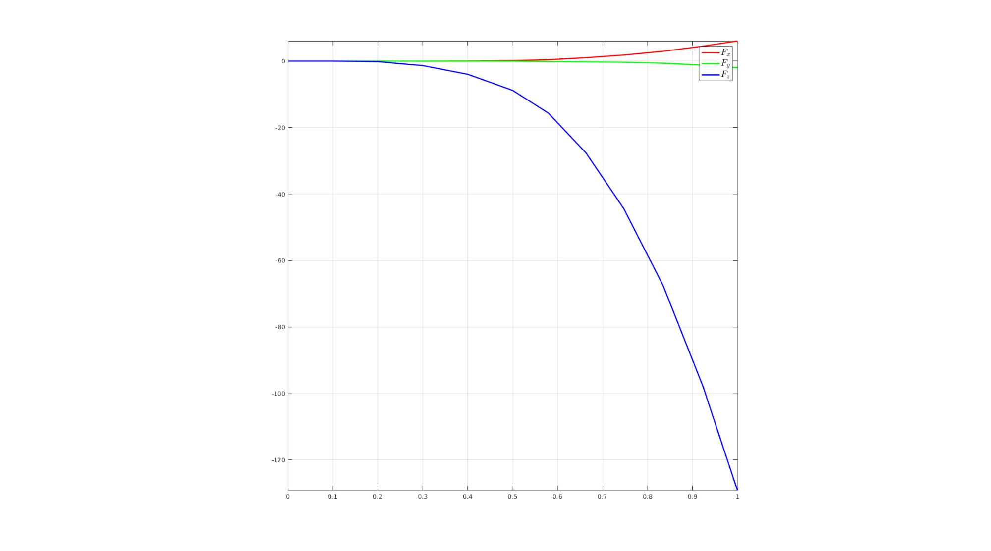
Import rigid body reaction forces
dataStructForce=importFEBio_logfile(fullfile(savePath,febioLogFileName_force),0,1);
F_reaction=squeeze(dataStructForce.data(1,:,:))';
timeVec=dataStructForce.time;
Visualize force
cFigure; hold on;
hp(1)=plot(timeVec,F_reaction(:,1),'r-','LineWidth',lineWidth);
hp(2)=plot(timeVec,F_reaction(:,2),'g-','LineWidth',lineWidth);
hp(3)=plot(timeVec,F_reaction(:,3),'b-','LineWidth',lineWidth);
hl=legend(hp,{'$F_x$','$F_y$','$F_z$'},'Interpreter','Latex','FontSize',fontSize);
axis square; axis tight; grid on; box on;
drawnow;
Importing nodal displacements from a log file
dataStructDisp=importFEBio_logfile(fullfile(savePath,febioLogFileName_disp),0,1);

%Access data
N_disp_mat=dataStructDisp.data; %Displacement
timeVec=dataStructDisp.time; %Time

%Create deformed coordinate set
V_DEF=N_disp_mat+repmat(V,[1 1 size(N_disp_mat,3)]);
Importing element stress from a log file
dataStruct=importFEBio_logfile(fullfile(savePath,febioLogFileName_sed),0,1);

%Access data
E_sed_mat=dataStruct.data;
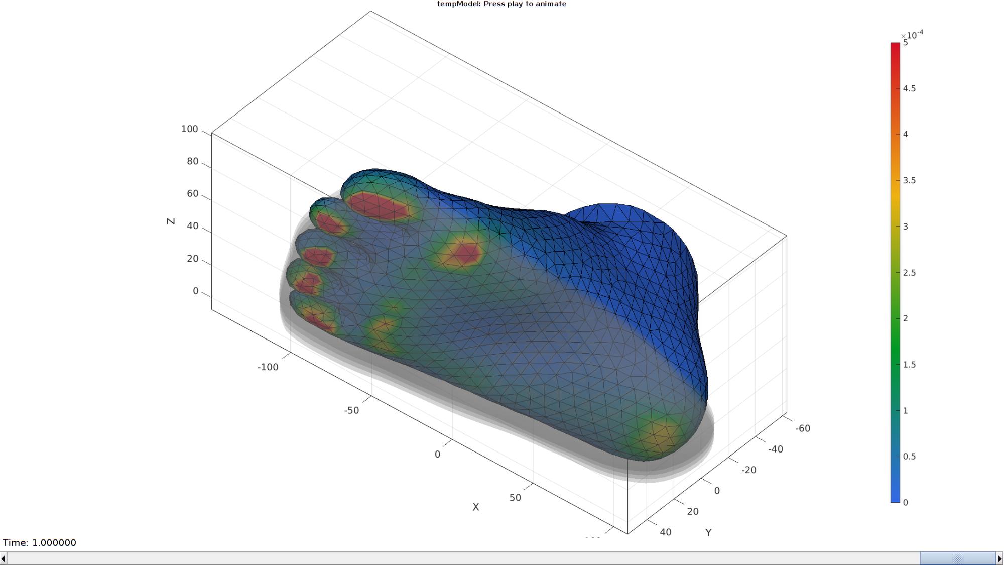
Plot animation
Plotting the simulated results using anim8 to visualize and animate deformations
[CV]=faceToVertexMeasure(E_foot,V,E_sed_mat(:,:,end));

% Create basic view and store graphics handle to initiate animation
hf=cFigure; hold on; %Open figure
gtitle([febioFebFileNamePart,': Press play to animate']);

hp1=gpatch(Fb_foot,V_DEF(:,:,end),CV,'k',1); %Add graphics object to animate
hp1.FaceColor='Interp';
hp2=gpatch(F_E_sole{1},V_DEF(:,:,end),'kw','none',0.25); %Add graphics object to animate

axisGeom(gca,fontSize);
colormap(gjet(250)); colorbar;
% caxis([0 max(C_energy_foot)/100]);
caxis([0 maxLevelColorbar_SED]);
axis(axisLim(V_DEF)); %Set axis limits statically
view([-40 -40]);
camlight headlight;

% Set up animation features
animStruct.Time=timeVec; %The time vector
for qt=1:1:size(V_DEF,3) %Loop over time increments

    [CV]=faceToVertexMeasure(E_foot,V,E_sed_mat(:,:,qt));

    %Set entries in animation structure
    animStruct.Handles{qt}=[hp1 hp1 hp2]; %Handles of objects to animate
    animStruct.Props{qt}={'Vertices','CData','Vertices'}; %Properties of objects to animate
    animStruct.Set{qt}={V_DEF(:,:,qt),CV,V_DEF(:,:,qt)}; %Property values for to set in order to animate
end
anim8(hf,animStruct); %Initiate animation feature
drawnow;

GIBBON www.gibboncode.org
Kevin Mattheus Moerman, [email protected]
GIBBON footer text
License: https://github.com/gibbonCode/GIBBON/blob/master/LICENSE
GIBBON: The Geometry and Image-based Bioengineering add-On. A toolbox for image segmentation, image-based modeling, meshing, and finite element analysis.
Copyright (C) 2006-2022 Kevin Mattheus Moerman and the GIBBON contributors
This program is free software: you can redistribute it and/or modify it under the terms of the GNU General Public License as published by the Free Software Foundation, either version 3 of the License, or (at your option) any later version.
This program is distributed in the hope that it will be useful, but WITHOUT ANY WARRANTY; without even the implied warranty of MERCHANTABILITY or FITNESS FOR A PARTICULAR PURPOSE. See the GNU General Public License for more details.
You should have received a copy of the GNU General Public License along with this program. If not, see http://www.gnu.org/licenses/.