DEMO_febio_0047_cylinder_embedded_probe_01
Below is a demonstration for:
- Building geometry for a tissue segment with an embedded probe
- Defining the boundary conditions
- Coding the febio structure
- Running the model
- Importing and visualizing the displacement results
Contents
Keywords
- febio_spec version 4.0
- febio, FEBio
- probe
- rigid body constraints
- tetrahedral elements, tet4
- triangular elements, tri3
- slab, block, rectangular
- sphere
- static, solid
- hyperelastic, Ogden
- displacement logfile
- stress logfile
clear; close all; clc;
Plot settings
fontSize=15;
faceAlpha=1;
lineWidth1=1.5;
lineWidth2=3;
markerSize1=15;
markerSize2=30;
edgeWidth=2;
edgeColor='k';
faceAlpha1=1;
cMap=spectral(250);
Control parameters
% Path names
defaultFolder = fileparts(fileparts(mfilename('fullpath')));
savePath=fullfile(defaultFolder,'data','temp');

% Defining file names
febioFebFileNamePart='tempModel';
febioFebFileName=fullfile(savePath,[febioFebFileNamePart,'.feb']); %FEB file name
febioLogFileName=[febioFebFileNamePart,'.txt']; %FEBio log file name
febioLogFileName_disp=[febioFebFileNamePart,'_disp_out.txt']; %Log file name for exporting displacement
febioLogFileName_force=[febioFebFileNamePart,'_force_out.txt']; %Log file name for exporting force
febioLogFileName_strainEnergy=[febioFebFileNamePart,'_energy_out.txt']; %Log file name for exporting strain energy density
febioLogFileName_strain=[febioFebFileNamePart,'_strain_out.txt']; %Log file name for exporting strain

probeHeight=75;

probeRadius=2; % The radius of the hemi-spher portion
nRefine=0; % Number of |subtri| refinements for icosahedron

pointSpacing=3;
dAdd=7;
tissueRadius=probeRadius+dAdd;
tissueHeight=probeHeight+dAdd;
volumeFactor=5;

displacementMagnitude=-1;

%Material parameter set
c1=1e-3; %Shear-modulus-like parameter
m1=2; %Material parameter setting degree of non-linearity
k_factor=1e2; %Bulk modulus factor
k=c1*k_factor; %Bulk modulus

% FEA control settings
numTimeSteps=10; %Number of time steps desired
max_refs=25; %Max reforms
max_ups=0; %Set to zero to use full-Newton iterations
opt_iter=6; %Optimum number of iterations
max_retries=5; %Maximum number of retires
dtmin=(1/numTimeSteps)/100; %Minimum time step size
dtmax=1/numTimeSteps; %Maximum time step size

runMode='external';% 'internal' or 'external'
Build probe
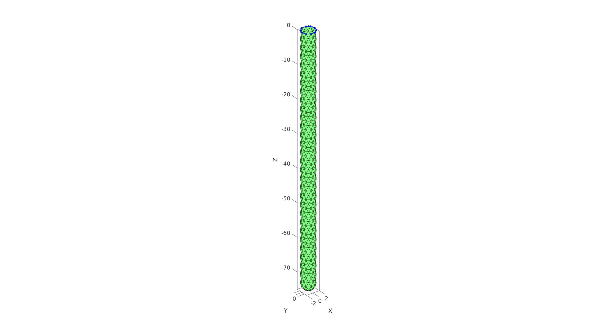
probeMeshInputStruct.sphereRadius=probeRadius;% => The radius of the hemi-spher portion
probeMeshInputStruct.nRefine=nRefine;% => Number of |subtri| refinements for icosahedron
probeMeshInputStruct.cylinderHeight=probeHeight-probeRadius;% => height of the cylinder part
probeMeshInputStruct.cylinderStepSize=[];% => Aproximate node spacing for cylinder portion
probeMeshInputStruct.patchType='tri';

[Fp,Vp,Cp]=hemiSphereCylMesh(probeMeshInputStruct);
Fp=fliplr(Fp); %Invert face orientation

Vp(:,3)=Vp(:,3)-max(Vp(:,3));

%Get top curve
Eb=patchBoundary(Fp);
indProbeTop=edgeListToCurve(Eb);
indProbeTop=indProbeTop(1:end-1);
Vst=Vp(indProbeTop,:);
cFigure; hold on;
gpatch(Fp,Vp,'gw','k');
plotV(Vst,'b.-','lineWidth',lineWidth1,'MarkerSize',markerSize1);
patchNormPlot(Fp,Vp);
axisGeom(gca,fontSize);
drawnow;
Build tissue
%Sketching profile
ns=150;
t=linspace(0,2*pi,ns);
t=t(1:end-1);

x=tissueRadius*cos(t);
y=tissueRadius*sin(t);
z=zeros(size(x));
Vc=[x(:) y(:) z(:)];
np=ceil(max(pathLength(Vc))./pointSpacing);
[Vc]=evenlySampleCurve(Vc,np,'pchip',1);

% Extruding model
cPar.numSteps=round(tissueHeight/pointSpacing);
cPar.depth=tissueHeight;
cPar.patchType='tri';
cPar.dir=-1;
cPar.closeLoopOpt=1;
[Fg,Vg]=polyExtrude(Vc,cPar);
Fg=fliplr(Fg);

Vgb=Vg(cPar.numSteps:cPar.numSteps:end,:);

Vgt=Vg(1:cPar.numSteps:end,:);
Cap ends
regionCell={Vgt(:,[1 2]),Vst(:,[1 2])};
[Ft,Vt]=regionTriMesh2D(regionCell,pointSpacing,0,0);
Vt(:,3)=mean(Vgt(:,3));

regionCell={Vgb(:,[1 2])};
[Fb,Vb]=regionTriMesh2D(regionCell,pointSpacing,0,0);
Fb=fliplr(Fb); %flip face orientation
Vb(:,3)=mean(Vgb(:,3));
Visualize
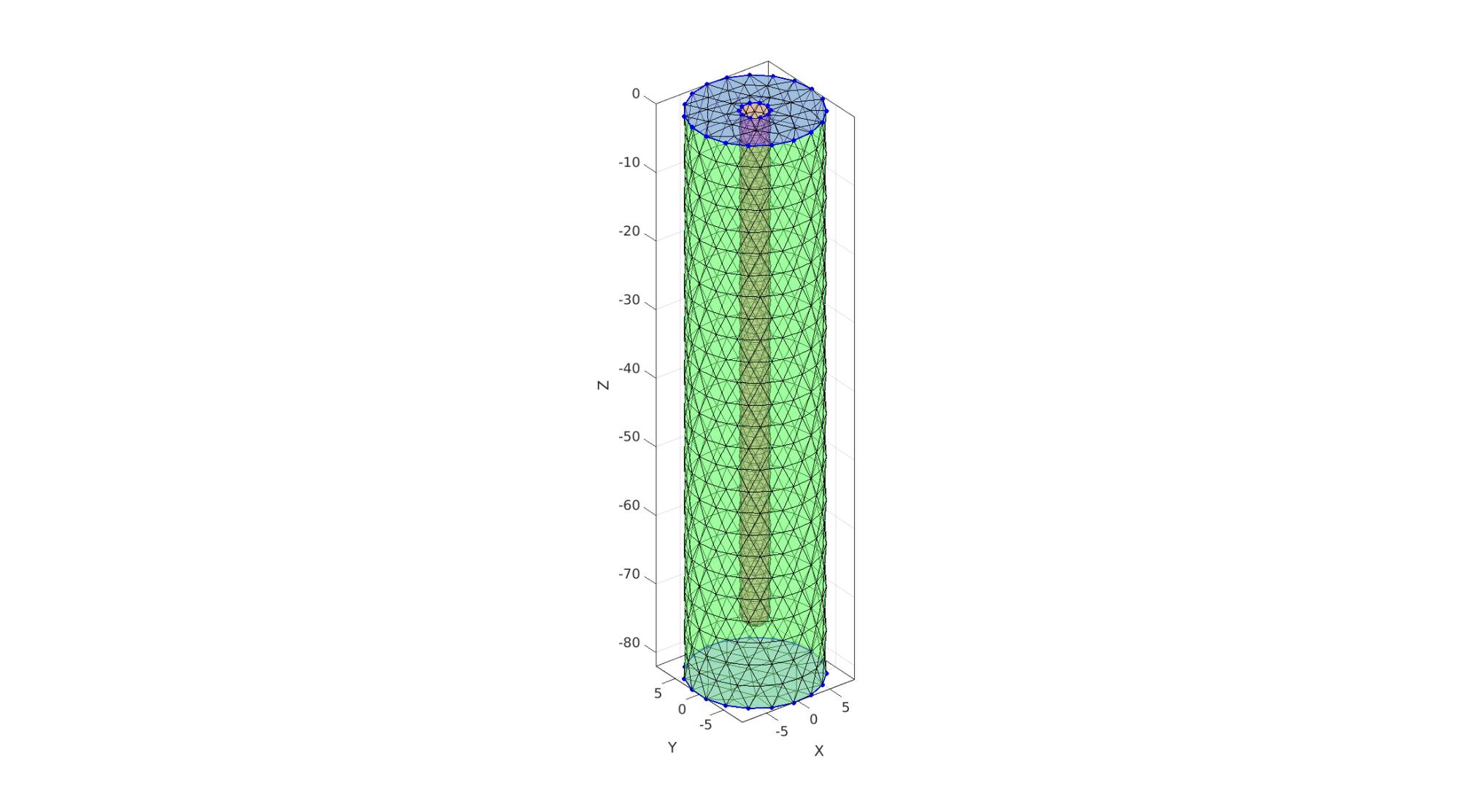
cFigure; hold on;

gpatch(Fp,Vp,'rw','k',0.5);
gpatch(Fg,Vg,'gw','k',0.5);
gpatch(Fb,Vb,'bw','k',0.5);
gpatch(Ft,Vt,'bw','k',0.5);

plotV(Vgb,'b.-','lineWidth',lineWidth1,'MarkerSize',markerSize1);
plotV(Vgt,'b.-','lineWidth',lineWidth1,'MarkerSize',markerSize1);
plotV(Vst,'b.-','lineWidth',lineWidth1,'MarkerSize',markerSize1);

axisGeom(gca,fontSize);
drawnow;
Merge model components
[F,V,C]=joinElementSets({Fg,Ft,Fb,Fp},{Vg,Vt,Vb,Vp});
[F,V]=mergeVertices(F,V);
cFigure;
subplot(1,2,1); hold on;
gpatch(F,V,C,'none',0.5);
axisGeom(gca,fontSize);
colormap gjet; icolorbar;

subplot(1,2,2); hold on;
gpatch(F,V,C);
patchNormPlot(F,V,2);
plotV(Vst,'b.-','lineWidth',lineWidth1,'MarkerSize',markerSize1);
axisGeom(gca,fontSize);
colormap gjet; icolorbar;

drawnow;
Mesh solid using tetgen
Create tetgen meshing input structure
[regionA]=tetVolMeanEst(F,V); %Volume for a regular tet based on edge lengths
V_inner=getInnerPoint(F,V); %Interior point for region

inputStruct.stringOpt='-pq1.2AaY';
inputStruct.Faces=F;
inputStruct.Nodes=V;
inputStruct.holePoints=[];
inputStruct.faceBoundaryMarker=C; %Face boundary markers
inputStruct.regionPoints=V_inner; %region points
inputStruct.regionA=regionA*volumeFactor; %Desired volume for tets
inputStruct.minRegionMarker=2; %Minimum region marker
Mesh model using tetrahedral elements using tetGen
[meshOutput]=runTetGen(inputStruct); %Run tetGen
%%%%%%%%%%%%%%%%%%%%%%%%%%%%%%%%%%%%%%%%%%%%%
--- TETGEN Tetrahedral meshing --- 20-Apr-2023 18:10:16

%%%%%%%%%%%%%%%%%%%%%%%%%%%%%%%%%%%%%%%%%%%%%
--- Writing SMESH file --- 20-Apr-2023 18:10:16
----> Adding node field
----> Adding facet field
----> Adding holes specification
----> Adding region specification
--- Done --- 20-Apr-2023 18:10:17
--- Running TetGen to mesh input boundary--- 20-Apr-2023 18:10:17
Opening /mnt/data/MATLAB/GIBBON/data/temp/temp.smesh.
Delaunizing vertices...
Delaunay seconds:  0.05929
Creating surface mesh ...
Surface mesh seconds:  0.001515
Recovering boundaries...
Boundary recovery seconds:  0.004271
Removing exterior tetrahedra ...
Warning:  The 1-th region point lies outside the convex hull.
Spreading region attributes.
Exterior tets removal seconds:  0.001275
Recovering Delaunayness...
Delaunay recovery seconds:  0.0017
Refining mesh...
  1548 insertions, added 764 points, 15046 tetrahedra in queue.
Refinement seconds:  0.023373
Smoothing vertices...
Mesh smoothing seconds:  0.035534
Improving mesh...
Mesh improvement seconds:  0.001778

Writing /mnt/data/MATLAB/GIBBON/data/temp/temp.1.node.
Writing /mnt/data/MATLAB/GIBBON/data/temp/temp.1.ele.
Writing /mnt/data/MATLAB/GIBBON/data/temp/temp.1.face.
Writing /mnt/data/MATLAB/GIBBON/data/temp/temp.1.edge.

Output seconds:  0.02143
Total running seconds:  0.150301

Statistics:

  Input points: 1162
  Input facets: 2320
  Input segments: 3480
  Input holes: 0
  Input regions: 1

  Mesh points: 1979
  Mesh tetrahedra: 8572
  Mesh faces: 18304
  Mesh faces on exterior boundary: 2320
  Mesh faces on input facets: 2320
  Mesh edges on input segments: 3480
  Steiner points inside domain: 817

--- Done --- 20-Apr-2023 18:10:17

%%%%%%%%%%%%%%%%%%%%%%%%%%%%%%%%%%%%%%%%%%%%%
--- Importing TetGen files --- 20-Apr-2023 18:10:17
--- Done --- 20-Apr-2023 18:10:17
Visualize mesh
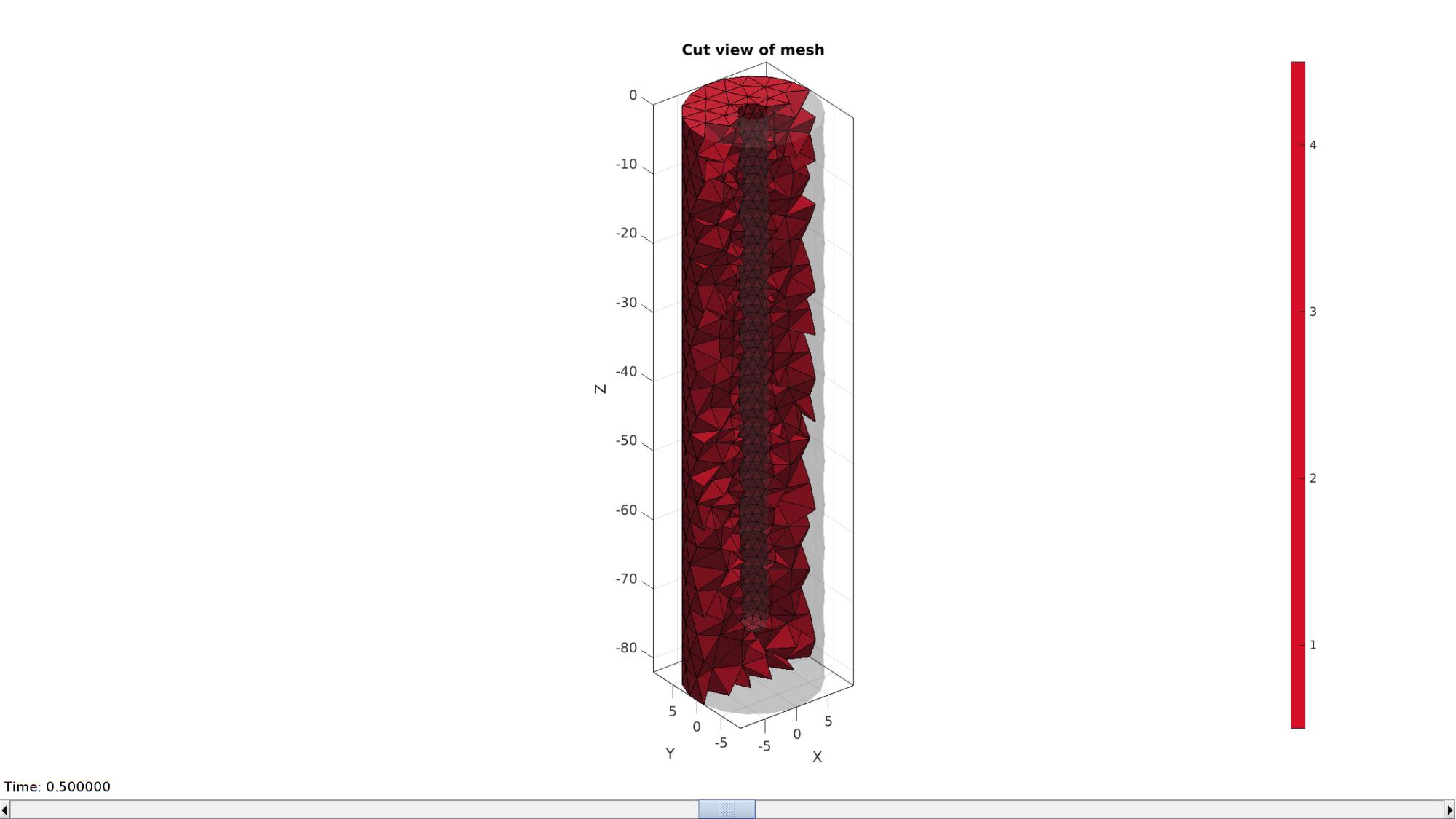
meshView(meshOutput);
Access model element and patch data
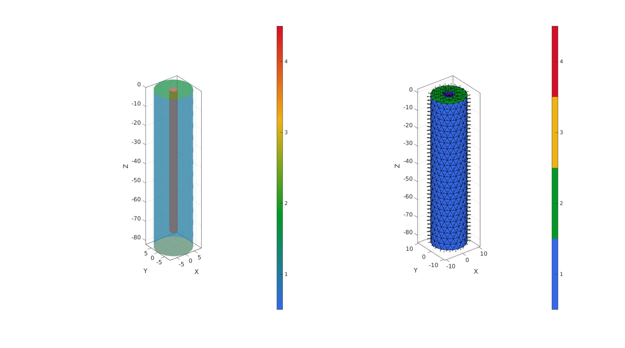
F=meshOutput.faces;
V=meshOutput.nodes;
C=meshOutput.faceMaterialID;
E=meshOutput.elements;
elementMaterialID=meshOutput.elementMaterialID;

Fb=meshOutput.facesBoundary;
Cb=meshOutput.boundaryMarker;
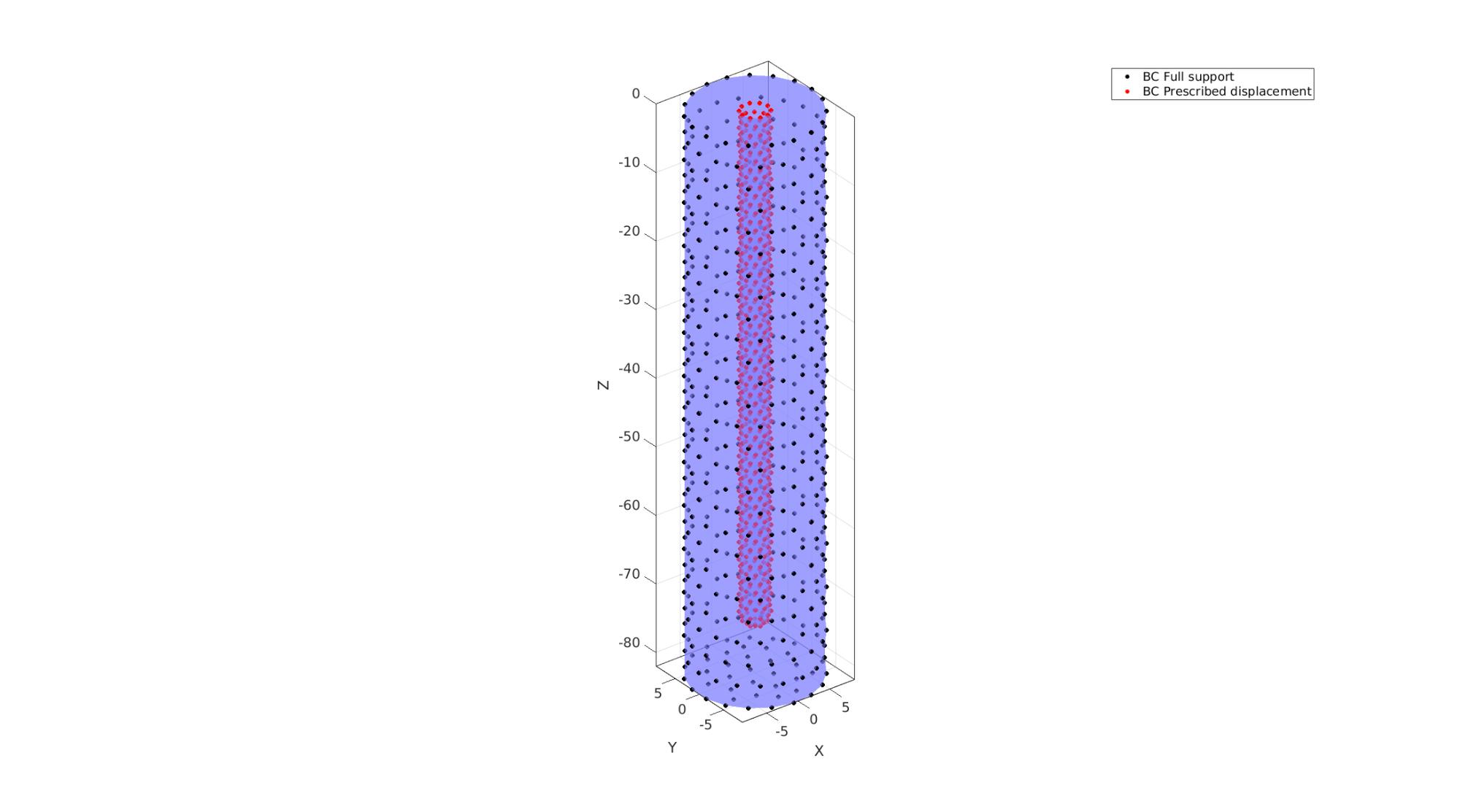
Define boundary condition node sets
logicRigid= Cb==1 | Cb==3;
bcSupportList=Fb(logicRigid,:);
bcSupportList=unique(bcSupportList(:));

logicIndentor= Cb==4;
bcPrescribeList=Fb(logicIndentor,:);
bcPrescribeList=unique(bcPrescribeList(:));
Visualize boundary conditions
cFigure; hold on;
gpatch(Fb,V,'bw','none',0.5);
hp(1)=plotV(V(bcSupportList,:),'k.','lineWidth',lineWidth1,'MarkerSize',markerSize1);
hp(2)=plotV(V(bcPrescribeList,:),'r.','lineWidth',lineWidth1,'MarkerSize',markerSize1);
legend(hp,{'BC Full support','BC Prescribed displacement'});
axisGeom(gca,fontSize);
drawnow;
Defining the FEBio input structure
See also febioStructTemplate and febioStruct2xml and the FEBio user manual.
%Get a template with default settings
[febio_spec]=febioStructTemplate;

%febio_spec version
febio_spec.ATTR.version='4.0';

%Module section
febio_spec.Module.ATTR.type='solid';

%Create control structure for use by all steps
stepStruct.Control.time_steps=numTimeSteps;
stepStruct.Control.step_size=1/numTimeSteps;
stepStruct.Control.solver.max_refs=max_refs;
stepStruct.Control.time_stepper.dtmin=dtmin;
stepStruct.Control.time_stepper.dtmax=dtmax;
stepStruct.Control.time_stepper.max_retries=max_retries;
stepStruct.Control.time_stepper.opt_iter=opt_iter;

%Add template based default settings to proposed control section
[stepStruct.Control]=structComplete(stepStruct.Control,febio_spec.Control,1); %Complement provided with default if missing

%Remove control field (part of template) since step specific control sections are used
febio_spec=rmfield(febio_spec,'Control');

febio_spec.Step.step{1}.Control=stepStruct.Control;
febio_spec.Step.step{1}.ATTR.id=1;
febio_spec.Step.step{2}.Control=stepStruct.Control;
febio_spec.Step.step{2}.ATTR.id=2;

%Material section
materialName1='Material1';
febio_spec.Material.material{1}.ATTR.name=materialName1;
febio_spec.Material.material{1}.ATTR.type='Ogden';
febio_spec.Material.material{1}.ATTR.id=1;
febio_spec.Material.material{1}.c1=c1;
febio_spec.Material.material{1}.m1=m1;
febio_spec.Material.material{1}.c2=c1;
febio_spec.Material.material{1}.m2=-m1;
febio_spec.Material.material{1}.k=k;
% Mesh section
% -> Nodes
febio_spec.Mesh.Nodes{1}.ATTR.name='Object1'; %The node set name
febio_spec.Mesh.Nodes{1}.node.ATTR.id=(1:size(V,1))'; %The node id's
febio_spec.Mesh.Nodes{1}.node.VAL=V; %The nodel coordinates

% -> Elements
partName1='Part1';
febio_spec.Mesh.Elements{1}.ATTR.name=partName1; %Name of this part
febio_spec.Mesh.Elements{1}.ATTR.type='tet4'; %Element type
febio_spec.Mesh.Elements{1}.elem.ATTR.id=(1:1:size(E,1))'; %Element id's
febio_spec.Mesh.Elements{1}.elem.VAL=E; %The element matrix

% -> NodeSets
nodeSetName1='bcSupportList';
nodeSetName2='bcPrescribeList';

febio_spec.Mesh.NodeSet{1}.ATTR.name=nodeSetName1;
febio_spec.Mesh.NodeSet{1}.VAL=mrow(bcSupportList);

febio_spec.Mesh.NodeSet{2}.ATTR.name=nodeSetName2;
febio_spec.Mesh.NodeSet{2}.VAL=mrow(bcPrescribeList);

%MeshDomains section
febio_spec.MeshDomains.SolidDomain.ATTR.name=partName1;
febio_spec.MeshDomains.SolidDomain.ATTR.mat=materialName1;

%Boundary condition section
% -> Fix boundary conditions
febio_spec.Boundary.bc{1}.ATTR.name='zero_displacement_xyz';
febio_spec.Boundary.bc{1}.ATTR.type='zero displacement';
febio_spec.Boundary.bc{1}.ATTR.node_set=nodeSetName1;
febio_spec.Boundary.bc{1}.x_dof=1;
febio_spec.Boundary.bc{1}.y_dof=1;
febio_spec.Boundary.bc{1}.z_dof=1;

febio_spec.Boundary.bc{2}.ATTR.name='zero_displacement_xz';
febio_spec.Boundary.bc{2}.ATTR.type='zero displacement';
febio_spec.Boundary.bc{2}.ATTR.node_set=nodeSetName2;
febio_spec.Boundary.bc{2}.x_dof=0;
febio_spec.Boundary.bc{2}.y_dof=1;
febio_spec.Boundary.bc{2}.z_dof=1;

% -> Prescribe boundary conditions
%STEP 1 Up/down
febio_spec.Step.step{1}.Boundary.bc{1}.ATTR.name='bcPrescribeList1';
febio_spec.Step.step{1}.Boundary.bc{1}.ATTR.type='prescribed displacement';
febio_spec.Step.step{1}.Boundary.bc{1}.ATTR.node_set=nodeSetName2;
febio_spec.Step.step{1}.Boundary.bc{1}.dof='z';
febio_spec.Step.step{1}.Boundary.bc{1}.value.ATTR.lc=1;
febio_spec.Step.step{1}.Boundary.bc{1}.value.VAL=displacementMagnitude;
febio_spec.Step.step{1}.Boundary.bc{1}.relative=1;

febio_spec.Step.step{1}.Boundary.bc{2}.ATTR.name='FixedDisplacement21';
febio_spec.Step.step{1}.Boundary.bc{2}.ATTR.type='zero displacement';
febio_spec.Step.step{1}.Boundary.bc{2}.ATTR.node_set=nodeSetName2;
febio_spec.Step.step{1}.Boundary.bc{2}.x_dof=1;
febio_spec.Step.step{1}.Boundary.bc{2}.y_dof=1;
febio_spec.Step.step{1}.Boundary.bc{2}.z_dof=0;

%STEP 2 Left/right
febio_spec.Step.step{2}.Boundary.bc{1}.ATTR.name='bcPrescribeList2';
febio_spec.Step.step{2}.Boundary.bc{1}.ATTR.type='prescribed displacement';
febio_spec.Step.step{2}.Boundary.bc{1}.ATTR.node_set=nodeSetName2;
febio_spec.Step.step{2}.Boundary.bc{1}.dof='x';
febio_spec.Step.step{2}.Boundary.bc{1}.value.ATTR.lc=2;
febio_spec.Step.step{2}.Boundary.bc{1}.value.VAL=displacementMagnitude;
febio_spec.Step.step{2}.Boundary.bc{1}.relative=1;

febio_spec.Step.step{2}.Boundary.bc{2}.ATTR.name='FixedDisplacement22';
febio_spec.Step.step{2}.Boundary.bc{2}.ATTR.type='zero displacement';
febio_spec.Step.step{2}.Boundary.bc{2}.ATTR.node_set=nodeSetName2;
febio_spec.Step.step{2}.Boundary.bc{2}.x_dof=0;
febio_spec.Step.step{2}.Boundary.bc{2}.y_dof=1;
febio_spec.Step.step{2}.Boundary.bc{2}.z_dof=1;

%LoadData section
% -> load_controller
febio_spec.LoadData.load_controller{1}.ATTR.id=1;
febio_spec.LoadData.load_controller{1}.ATTR.name='LC1';
febio_spec.LoadData.load_controller{1}.ATTR.type='loadcurve';
febio_spec.LoadData.load_controller{1}.interpolate='LINEAR';
febio_spec.LoadData.load_controller{1}.extend='CONSTANT';
febio_spec.LoadData.load_controller{1}.points.pt.VAL=[0 0; 0.25 1; 0.5 0; 0.75 -1; 1 0];

febio_spec.LoadData.load_controller{2}.ATTR.id=2;
febio_spec.LoadData.load_controller{2}.ATTR.name='LC2';
febio_spec.LoadData.load_controller{2}.ATTR.type='loadcurve';
febio_spec.LoadData.load_controller{2}.interpolate='LINEAR';
febio_spec.LoadData.load_controller{2}.extend='CONSTANT';
febio_spec.LoadData.load_controller{2}.points.pt.VAL=[0 0; 1 0; 1.25 1; 1.5 0; 1.75 -1; 2 0];

%Output section
% -> log file
febio_spec.Output.logfile.ATTR.file=febioLogFileName;
febio_spec.Output.logfile.node_data{1}.ATTR.file=febioLogFileName_disp;
febio_spec.Output.logfile.node_data{1}.ATTR.data='ux;uy;uz';
febio_spec.Output.logfile.node_data{1}.ATTR.delim=',';

febio_spec.Output.logfile.node_data{2}.ATTR.file=febioLogFileName_force;
febio_spec.Output.logfile.node_data{2}.ATTR.data='Rx;Ry;Rz';
febio_spec.Output.logfile.node_data{2}.ATTR.delim=',';

febio_spec.Output.logfile.element_data{1}.ATTR.file=febioLogFileName_strain;
febio_spec.Output.logfile.element_data{1}.ATTR.data='E1;E2;E3';
febio_spec.Output.logfile.element_data{1}.ATTR.delim=',';

% Plotfile section
febio_spec.Output.plotfile.compression=0;
Quick viewing of the FEBio input file structure
The febView function can be used to view the xml structure in a MATLAB figure window.
febView(febio_spec); %Viewing the febio file
Exporting the FEBio input file
Exporting the febio_spec structure to an FEBio input file is done using the febioStruct2xml function.
febioStruct2xml(febio_spec,febioFebFileName); %Exporting to file and domNode
Running the FEBio analysis
To run the analysis defined by the created FEBio input file the runMonitorFEBio function is used. The input for this function is a structure defining job settings e.g. the FEBio input file name. The optional output runFlag informs the user if the analysis was run succesfully.
febioAnalysis.run_filename=febioFebFileName; %The input file name
febioAnalysis.run_logname=febioLogFileName; %The name for the log file
febioAnalysis.disp_on=1; %Display information on the command window
febioAnalysis.runMode=runMode;

[runFlag]=runMonitorFEBio(febioAnalysis);%START FEBio NOW!!!!!!!!
%%%%%%%%%%%%%%%%%%%%%%%%%%%%%%%%%%%%%%%%%%%%%%%%%%%%%%%%%%%%%%%%%%%%%%%%%%%
-------->    RUNNING/MONITORING FEBIO JOB    <-------- 20-Apr-2023 18:10:22
FEBio path: /home/kevin/FEBioStudio2/bin/febio4
# Attempt removal of existing log files                20-Apr-2023 18:10:22
 * Removal succesful                                   20-Apr-2023 18:10:22
# Attempt removal of existing .xplt files              20-Apr-2023 18:10:22
 * Removal succesful                                   20-Apr-2023 18:10:22
# Starting FEBio...                                    20-Apr-2023 18:10:22
  Max. total analysis time is: Inf s
 * Waiting for log file creation                       20-Apr-2023 18:10:22
   Max. wait time: 30 s
 * Log file found.                                     20-Apr-2023 18:10:22
# Parsing log file...                                  20-Apr-2023 18:10:22
    number of iterations   : 3                         20-Apr-2023 18:10:23
    number of reformations : 3                         20-Apr-2023 18:10:23
------- converged at time : 0.1                        20-Apr-2023 18:10:23
    number of iterations   : 3                         20-Apr-2023 18:10:23
    number of reformations : 3                         20-Apr-2023 18:10:23
------- converged at time : 0.2                        20-Apr-2023 18:10:23
    number of iterations   : 1                         20-Apr-2023 18:10:23
    number of reformations : 1                         20-Apr-2023 18:10:23
------- converged at time : 0.3                        20-Apr-2023 18:10:23
    number of iterations   : 3                         20-Apr-2023 18:10:23
    number of reformations : 3                         20-Apr-2023 18:10:23
------- converged at time : 0.4                        20-Apr-2023 18:10:23
    number of iterations   : 3                         20-Apr-2023 18:10:23
    number of reformations : 3                         20-Apr-2023 18:10:23
------- converged at time : 0.5                        20-Apr-2023 18:10:23
    number of iterations   : 3                         20-Apr-2023 18:10:24
    number of reformations : 3                         20-Apr-2023 18:10:24
------- converged at time : 0.6                        20-Apr-2023 18:10:24
    number of iterations   : 3                         20-Apr-2023 18:10:24
    number of reformations : 3                         20-Apr-2023 18:10:24
------- converged at time : 0.7                        20-Apr-2023 18:10:24
    number of iterations   : 1                         20-Apr-2023 18:10:24
    number of reformations : 1                         20-Apr-2023 18:10:24
------- converged at time : 0.8                        20-Apr-2023 18:10:24
    number of iterations   : 3                         20-Apr-2023 18:10:24
    number of reformations : 3                         20-Apr-2023 18:10:24
------- converged at time : 0.9                        20-Apr-2023 18:10:24
    number of iterations   : 3                         20-Apr-2023 18:10:24
    number of reformations : 3                         20-Apr-2023 18:10:24
------- converged at time : 1                          20-Apr-2023 18:10:24
    number of iterations   : 3                         20-Apr-2023 18:10:25
    number of reformations : 3                         20-Apr-2023 18:10:25
------- converged at time : 1.1                        20-Apr-2023 18:10:25
    number of iterations   : 3                         20-Apr-2023 18:10:25
    number of reformations : 3                         20-Apr-2023 18:10:25
------- converged at time : 1.2                        20-Apr-2023 18:10:25
    number of iterations   : 1                         20-Apr-2023 18:10:25
    number of reformations : 1                         20-Apr-2023 18:10:25
------- converged at time : 1.3                        20-Apr-2023 18:10:25
    number of iterations   : 4                         20-Apr-2023 18:10:26
    number of reformations : 4                         20-Apr-2023 18:10:26
------- converged at time : 1.4                        20-Apr-2023 18:10:26
    number of iterations   : 3                         20-Apr-2023 18:10:26
    number of reformations : 3                         20-Apr-2023 18:10:26
------- converged at time : 1.5                        20-Apr-2023 18:10:26
    number of iterations   : 3                         20-Apr-2023 18:10:26
    number of reformations : 3                         20-Apr-2023 18:10:26
------- converged at time : 1.6                        20-Apr-2023 18:10:26
    number of iterations   : 3                         20-Apr-2023 18:10:26
    number of reformations : 3                         20-Apr-2023 18:10:26
------- converged at time : 1.7                        20-Apr-2023 18:10:26
    number of iterations   : 1                         20-Apr-2023 18:10:26
    number of reformations : 1                         20-Apr-2023 18:10:26
------- converged at time : 1.8                        20-Apr-2023 18:10:26
    number of iterations   : 3                         20-Apr-2023 18:10:26
------- converged at time : 1.9                        20-Apr-2023 18:10:27
    number of iterations   : 4                         20-Apr-2023 18:10:27
    number of reformations : 4                         20-Apr-2023 18:10:27
------- converged at time : 2                          20-Apr-2023 18:10:27
 Elapsed time : 0:00:04                                20-Apr-2023 18:10:27
 N O R M A L   T E R M I N A T I O N
# Done                                                 20-Apr-2023 18:10:27
%%%%%%%%%%%%%%%%%%%%%%%%%%%%%%%%%%%%%%%%%%%%%%%%%%%%%%%%%%%%%%%%%%%%%%%%%%%
Import FEBio results
if runFlag==1 %i.e. a succesful run
Importing nodal displacements from a log file
    dataStruct=importFEBio_logfile(fullfile(savePath,febioLogFileName_disp),0,1);

    %Access data
    N_disp_mat=dataStruct.data; %Displacement
    timeVec=dataStruct.time; %Time

    %Create deformed coordinate set
    V_DEF=N_disp_mat+repmat(V,[1 1 size(N_disp_mat,3)]);
Importing element data from a log file
   dataStruct=importFEBio_logfile(fullfile(savePath,febioLogFileName_strain),0,1); %Element data
    E_data_mat=dataStruct.data;
    E_VM=sqrt(0.5*( (E_data_mat(:,1,:)-E_data_mat(:,2,:)).^2 + ...
                    (E_data_mat(:,2,:)-E_data_mat(:,3,:)).^2 + ...
                    (E_data_mat(:,3,:)-E_data_mat(:,1,:)).^2 ));
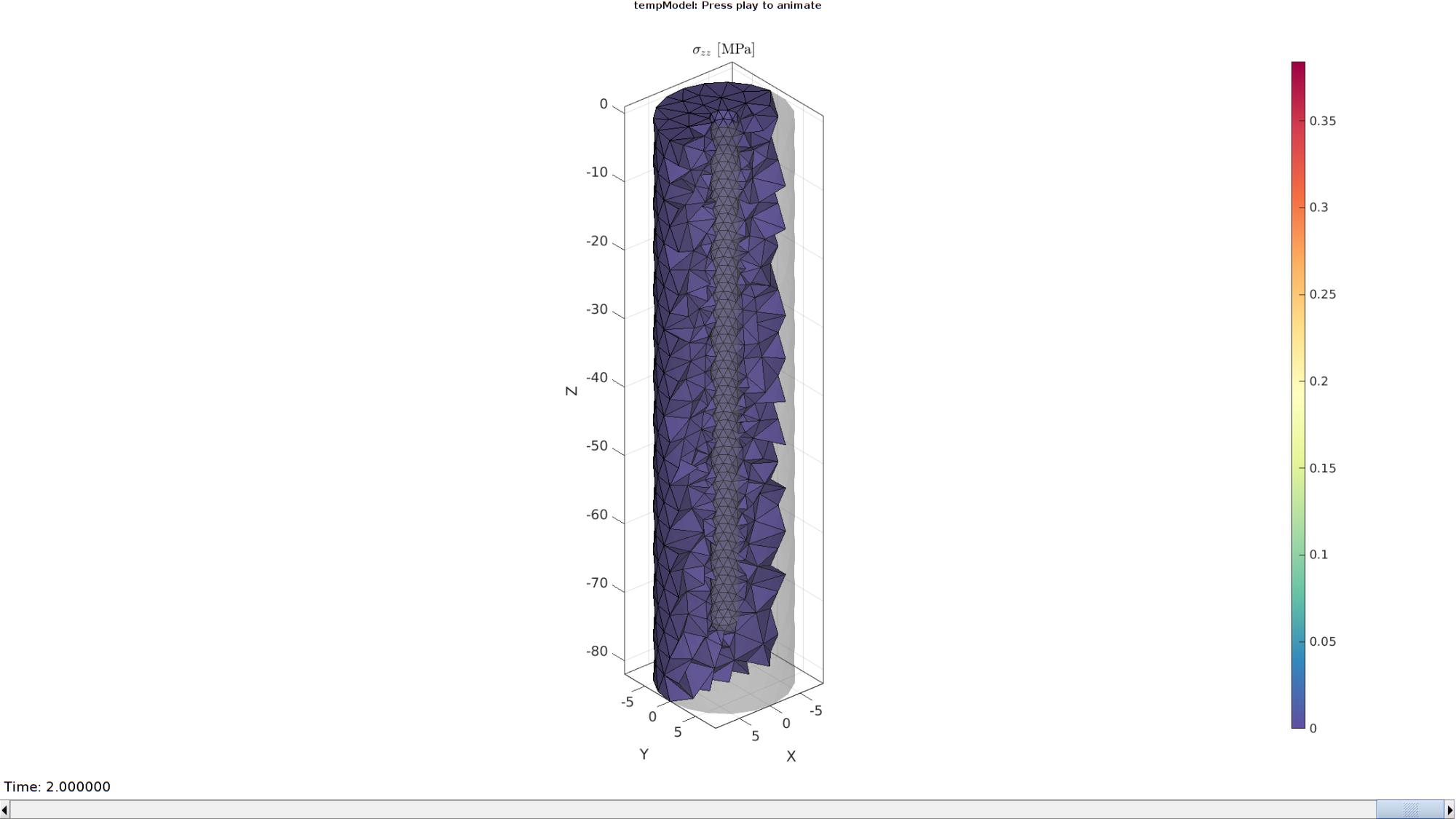
Plotting the simulated results using anim8 to visualize and animate deformations
    VE=patchCentre(E,V);
    logicCutElements=VE(:,2)<=0;

    [F_cut,CF_cut_data]=element2patch(E(logicCutElements,:),E_VM(logicCutElements,:,end));
    [indBoundary]=tesBoundary(F_cut);

    CV=faceToVertexMeasure(F_cut(indBoundary,:),V,CF_cut_data(indBoundary,:));

    % Create basic view and store graphics handle to initiate animation
    hf=cFigure; %Open figure  /usr/local/MATLAB/R2020a/bin/glnxa64/jcef_helper: symbol lookup error: /lib/x86_64-linux-gnu/libpango-1.0.so.0: undefined symbol: g_ptr_array_copy

    gtitle([febioFebFileNamePart,': Press play to animate']);
    title('$\sigma_{zz}$ [MPa]','Interpreter','Latex')
    hp1=gpatch(Fb,V_DEF(:,:,end),'kw','none',0.25); %Add graphics object to animate
    hp2=gpatch(F_cut(indBoundary,:),V_DEF(:,:,end),CV,'k',1); %Add graphics object to animate
    hp2.FaceColor='interp';

    gpatch(Fb,V,0.5*ones(1,3),'none',0.25); %A static graphics object

    axisGeom(gca,fontSize);
    colormap(cMap); colorbar;
    caxis([0 max(E_VM(:))/3]);
    axis(axisLim(V_DEF)); %Set axis limits statically
    view(140,30);
    camlight headlight;

    % Set up animation features
    animStruct.Time=timeVec; %The time vector
    for qt=1:1:size(N_disp_mat,3) %Loop over time increments
        [F_cut,CF_cut_data]=element2patch(E(logicCutElements,:),E_VM(logicCutElements,:,qt));
        CV=faceToVertexMeasure(F_cut(indBoundary,:),V,CF_cut_data(indBoundary,:));

        %Set entries in animation structure
        animStruct.Handles{qt}=[hp1 hp2 hp2]; %Handles of objects to animate
        animStruct.Props{qt}={'Vertices','Vertices','CData'}; %Properties of objects to animate
        animStruct.Set{qt}={V_DEF(:,:,qt),V_DEF(:,:,qt),CV}; %Property values for to set in order to animate
    end
    anim8(hf,animStruct); %Initiate animation feature
    drawnow;
end

GIBBON www.gibboncode.org
Kevin Mattheus Moerman, [email protected]
GIBBON footer text
License: https://github.com/gibbonCode/GIBBON/blob/master/LICENSE
GIBBON: The Geometry and Image-based Bioengineering add-On. A toolbox for image segmentation, image-based modeling, meshing, and finite element analysis.
Copyright (C) 2006-2022 Kevin Mattheus Moerman and the GIBBON contributors
This program is free software: you can redistribute it and/or modify it under the terms of the GNU General Public License as published by the Free Software Foundation, either version 3 of the License, or (at your option) any later version.
This program is distributed in the hope that it will be useful, but WITHOUT ANY WARRANTY; without even the implied warranty of MERCHANTABILITY or FITNESS FOR A PARTICULAR PURPOSE. See the GNU General Public License for more details.
You should have received a copy of the GNU General Public License along with this program. If not, see http://www.gnu.org/licenses/.