DEMO_febio_0031_blob_shear_contact
Below is a demonstration for:
- Building geometry for a hemi-spherical blob with tetrahedral elements which is being sheared by a rigid wall. This demo consists off:
- Defining the boundary conditions
- Coding the febio structure
- Running the model
- Importing and visualizing the displacement results
Contents
Keywords
- Abaqus
- indentation
- contact, sliding, sticky, friction
- rigid body constraints
- hexahedral elements
- hemisphere
- static, solid
- hyperelastic, Ogden
- displacement logfile
- stress logfile
clear; close all; clc;
Plot settings
fontSize=15;
faceAlpha1=0.8;
faceAlpha2=0.3;
markerSize=40;
lineWidth=3;
Control parameters
% Path names
defaultFolder = fileparts(fileparts(mfilename('fullpath')));
savePath=fullfile(defaultFolder,'data','temp');

% Defining file names
abaqusInpFileNamePart='tempModel';
abaqusInpFileName=fullfile(savePath,[abaqusInpFileNamePart,'.inp']); %INP file name

% Hemi-sphere parameters
hemiSphereRadius=1;
numElementsMantel=6;
closeOption=1;
smoothEdge=1;

% Ground plate parameters
plateRadius=2*hemiSphereRadius;

% Probe parameters
probeWidth=3*hemiSphereRadius;
filletProbe=0.5; %Fillet radius

% Define probe displacement
probeDisplacement=hemiSphereRadius*2;
proveOverlapFactor=0.4;

% Material parameter set
c1=1e-3; %Shear-modulus-like parameter
m1=8; %Material parameter setting degree of non-linearity
k_factor=1e2; %Bulk modulus factor
k=c1*k_factor; %Bulk modulus

% FEA control settings
numTimeSteps=15;
max_refs=25; %Max reforms
max_ups=0; %Set to zero to use full-Newton iterations
opt_iter=10; %Optimum number of iterations
max_retries=25; %Maximum number of retires
symmetric_stiffness=0;
min_residual=1e-20;
step_size=1/numTimeSteps;
dtmin=(1/numTimeSteps)/100; %Minimum time step size
dtmax=1/(numTimeSteps); %Maximum time step size

%Contact parameters
contactPenalty=20;
laugon=0;
minaug=1;
maxaug=10;
fric_coeff=0.1;
Creating model geometry and mesh
%Control settings
optionStruct.sphereRadius=1;
optionStruct.coreRadius=optionStruct.sphereRadius/2;
optionStruct.numElementsMantel=6;
optionStruct.numElementsCore=optionStruct.numElementsMantel*2;
optionStruct.outputStructType=2;
optionStruct.makeHollow=0;
optionStruct.cParSmooth.n=25;

% %Creating sphere
[meshStruct]=hexMeshHemiSphere(optionStruct);

% Access model element and patch data
Fb=meshStruct.facesBoundary;
Cb=meshStruct.boundaryMarker;
V=meshStruct.nodes;
E=meshStruct.elements;

F=element2patch(E);
pointSpacingBlob=mean(patchEdgeLengths(Fb,V));

%Smoothen edges
if smoothEdge==1
    %Get rigid region
    ind=1:1:size(V,1); %Indices for all nodes
    indRigid1=find(ismember(ind,Fb(Cb==2,:)) & ~ismember(ind,Fb(Cb==1,:))); %Indices for new bottom surface nodes
    indRigid2=find(ismember(ind,Fb(Cb==1,:)) & ~ismember(ind,Fb(Cb==2,:))); %Indices for new bottom surface nodes
    indRigid=[indRigid1(:); indRigid2(:);];

    %Smoothing
    cPar.Method='HC';
    cPar.n=250;
    cPar.RigidConstraints=indRigid;
    [Vb_blob]=patchSmooth(F,V,[],cPar);
    indSmooth=unique(F(:));
    V(indSmooth,:)=Vb_blob(indSmooth,:);
    %Fix color data with new bottom surface
    Cb=ones(size(Cb));
    Cb(all(ismember(Fb,indRigid1),2))=2;

    meshStruct.nodes=V;
end
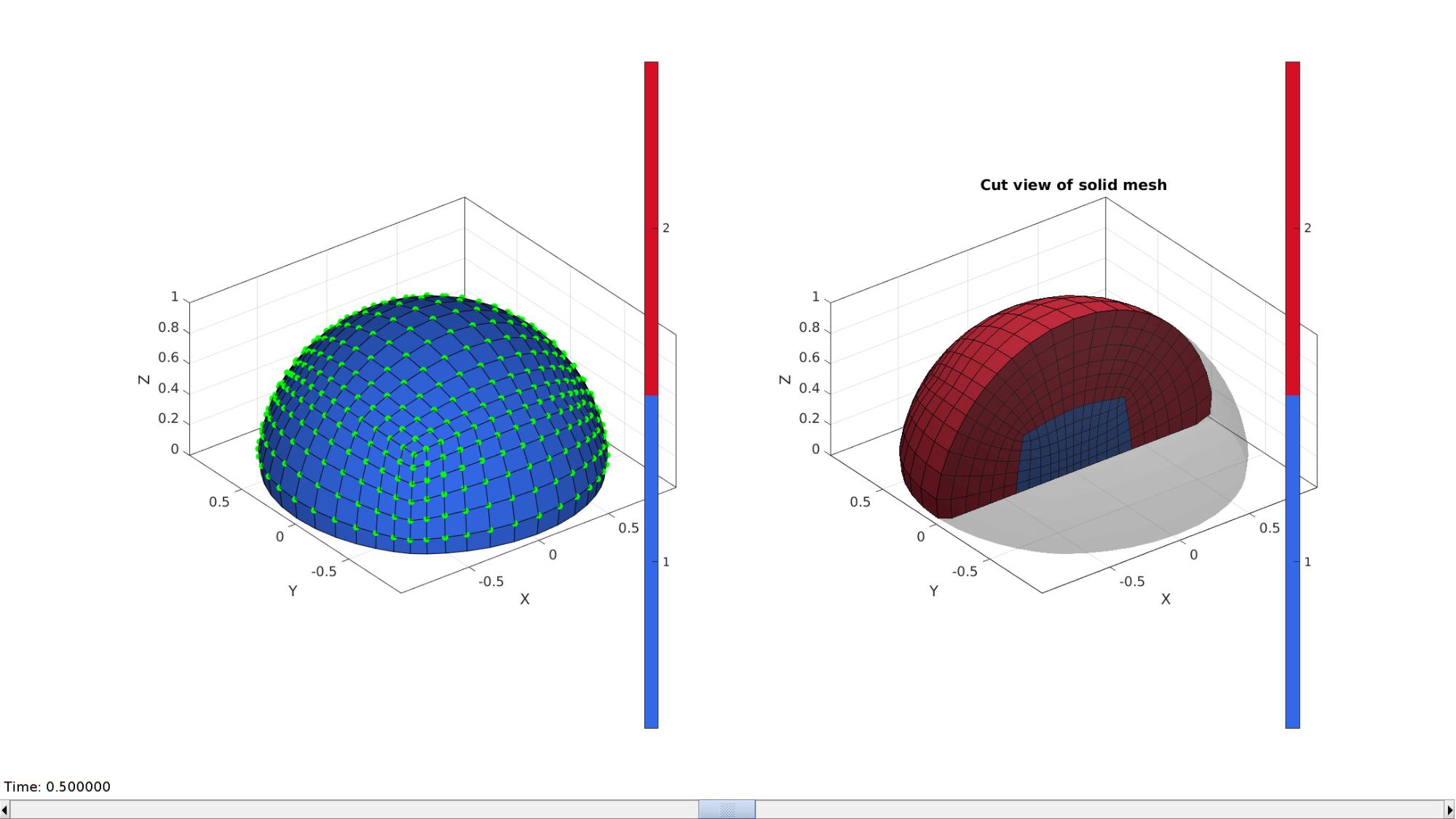
Visualize blob mesh
hFig=cFigure;
subplot(1,2,1); hold on;
gpatch(Fb,V,Cb,'k',1);
% patchNormPlot(Fb_blob,V_blob);
plotV(V(indRigid,:),'g.','MarkerSize',25);
axisGeom(gca,fontSize);
colormap(gjet); icolorbar;
camlight headlight;

hs=subplot(1,2,2); hold on;
title('Cut view of solid mesh','FontSize',fontSize);
optionStruct.hFig=[hFig hs];
gpatch(Fb,V,'kw','none',0.25);
meshView(meshStruct,optionStruct);
axisGeom(gca,fontSize);
drawnow;
Creating rigid body ground plate
%Get outer surve of ground surface
[Eb]=patchBoundary(Fb(Cb==2,:));
indCurveBottom=edgeListToCurve(Eb);
indCurveBottom=indCurveBottom(1:end-1);

% Derive point spacing for plate
pointSpacingPlate=pointSpacingBlob;

% Compose outer curve of the plate
nPlateCurve=ceil((2*pi*plateRadius)/pointSpacingPlate);
t=linspace(0,2*pi,nPlateCurve);
t=t(1:end-1);
x=plateRadius.*sin(t);
y=plateRadius.*cos(t);
V_plate_curve=[x(:) y(:) zeros(size(x(:)))];

center_of_mass_plate=mean(V_plate_curve,1);
Creating rigid body shear surface
pointSpacingProbe=pointSpacingBlob/2;

%Sketching side profile
x=[-hemiSphereRadius hemiSphereRadius hemiSphereRadius]-hemiSphereRadius*2;
y=[0 0 0];
z=[hemiSphereRadius*(1-proveOverlapFactor) hemiSphereRadius*(1-proveOverlapFactor) hemiSphereRadius*1.5];
V_probe_curve_sketch=[x(:) y(:) z(:)];

%Fillet sketch
np=100; %Number of points used to construct each fillet edge
[V_probe_curve]=filletCurve(V_probe_curve_sketch,filletProbe,np,0);
% numPointsProbeCurve=ceil(max(pathLength(V_probe_curve))/pointSpacingProbe);
% [V_probe_curve] = evenlySampleCurve(V_probe_curve,numPointsProbeCurve,'pchip',0);

center_of_mass_probe=mean(V_probe_curve,1);

V_probe_curve_1=V_probe_curve(1,:);
V_probe_curve_2=V_probe_curve(2,:);
V_probe_curve_3=V_probe_curve(2+np-1,:);
V_probe_curve_4=V_probe_curve(2,:);
V_probe_curve_4(:,3)=V_probe_curve_4(:,3)+filletProbe;
V_probe_curve_5=V_probe_curve(end,:);
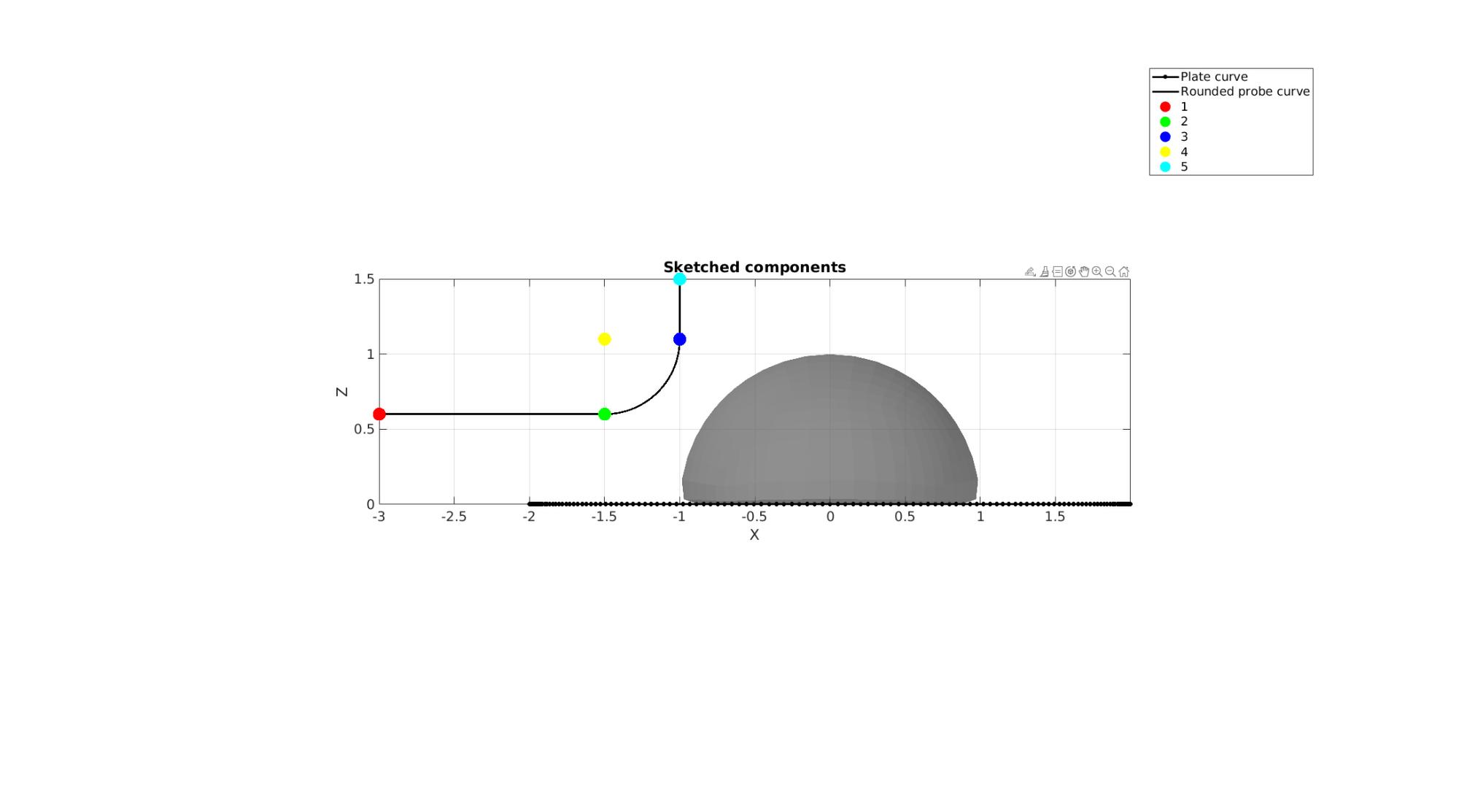
Visualizing curves
cFigure; hold on;
title('Sketched components','fontSize',fontSize);
gpatch(Fb,V,'kw','none',0.5);
hl(1)=plotV(V_plate_curve,'k.-','lineWidth',2,'MarkerSize',15);
hl(2)=plotV(V_probe_curve,'k-','lineWidth',2);
hl(3)=plotV(V_probe_curve_1,'r.','MarkerSize',50);
hl(4)=plotV(V_probe_curve_2,'g.','MarkerSize',50);
hl(5)=plotV(V_probe_curve_3,'b.','MarkerSize',50);
hl(6)=plotV(V_probe_curve_4,'y.','MarkerSize',50);
hl(7)=plotV(V_probe_curve_5,'c.','MarkerSize',50);
legend(hl,{'Plate curve','Rounded probe curve','1','2','3','4','5'}); clear hl;
axisGeom(gca,fontSize);
camlight headlight;
view(0,0);
drawnow;

Defining the abaqus input structure
See also abaqusStructTemplate and abaqusStruct2inp and the abaqus user manual.
%%--> Heading
abaqus_spec.Heading.COMMENT{1}='Job name: ABAQUS inp file creation demo';
abaqus_spec.Heading.COMMENT{2}='Generated by: GIBBON';

%%--> Preprint
abaqus_spec.Preprint.ATTR.echo='NO';
abaqus_spec.Preprint.ATTR.model='NO';
abaqus_spec.Preprint.ATTR.history='NO';
abaqus_spec.Preprint.ATTR.contact='NO';

%--> Part

% Node
nodeIds=(1:1:size(V,1))';
abaqus_spec.Part{1}.COMMENT='This section defines the part geometry in terms of nodes and elements';
abaqus_spec.Part{1}.ATTR.name='Blob';
abaqus_spec.Part{1}.Node={nodeIds,V};

% Element
elementIds=(1:1:size(E,1))';
abaqus_spec.Part{1}.Element{1}.ATTR.type='C3D8';%'C3D8R';
abaqus_spec.Part{1}.Element{1}.VAL={elementIds,E};

% Element sets
abaqus_spec.Part{1}.Elset{1}.ATTR.elset='Set-1';
abaqus_spec.Part{1}.Elset{1}.VAL=elementIds';

% Sections
abaqus_spec.Part{1}.Solid_section.ATTR.elset='Set-1';
abaqus_spec.Part{1}.Solid_section.ATTR.material='Elastic';

%Surfaces
abaqus_spec.Part{2}.COMMENT='This section defines the part geometry in terms of nodes and elements';
abaqus_spec.Part{2}.ATTR.name='rigid_surface';
abaqus_spec.Part{2}.Node={1,V_probe_curve_1};

abaqus_spec.Part{2}.surface.ATTR.type='cylinder';
abaqus_spec.Part{2}.surface.ATTR.name='probe_surface';
abaqus_spec.Part{2}.surface.VAL{1,1}={[0 0 0],[1 0 0]};
abaqus_spec.Part{2}.surface.VAL{2,1}={[0 1 0]};
abaqus_spec.Part{2}.surface.VAL{3,1}={{'start';'line';},[V_probe_curve_1(:,[1 3]);V_probe_curve_2(:,[1 3]);]};
abaqus_spec.Part{2}.surface.VAL{4,1}={{'circl'},[V_probe_curve_3(:,[1 3]) V_probe_curve_4(:,[1 3])]};
abaqus_spec.Part{2}.surface.VAL{5,1}={{'line'},V_probe_curve_5(:,[1 3])};

% Rigid body
%RIGID BODY, ANALYTICAL SURFACE=name, REF NODE=n
abaqus_spec.Part{2}.rigid_body.ATTR.analytical_surface='probe_surface';
abaqus_spec.Part{2}.rigid_body.ATTR.ref_node=1;


%%--> Assembly
abaqus_spec.Assembly{1}.ATTR.name='Assembly-1';
abaqus_spec.Assembly{1}.Instance{1}.ATTR.name='Blob-assembly';
abaqus_spec.Assembly{1}.Instance{1}.ATTR.part='Blob';
abaqus_spec.Assembly{1}.Instance{2}.ATTR.name='rigid_surface-assembly';
abaqus_spec.Assembly{1}.Instance{2}.ATTR.part='rigid_surface';
abaqus_spec.Assembly{1}.Instance{2}.VAL{1,1}={[0 0 0]};
abaqus_spec.Assembly{1}.Instance{2}.VAL{2,1}={[0 0 0 1 0 0 90]};

% abaqus_spec.Assembly{1}.Nset{1}.ATTR.nset='All';
% abaqus_spec.Assembly{1}.Nset{1}.ATTR.instance=abaqus_spec.Assembly{1}.Instance{1}.ATTR.name;
% abaqus_spec.Assembly{1}.Nset{1}.VAL=[1:1:size(V,1)];

% % Rigid body
% %RIGID BODY, ANALYTICAL SURFACE=name, REF NODE=n
% abaqus_spec.Assembly{1}.rigid_body.ATTR.analytical_surface='probe_surface';
% abaqus_spec.Assembly{1}.rigid_body.ATTR.ref_node=1;

%%--> Material
abaqus_spec.Material{1}.ATTR.name='Elastic';
abaqus_spec.Material{1}.Elastic=[1 0.45];

%%--> Step
abaqus_spec.Step.ATTR.name='Step-1';
abaqus_spec.Step.ATTR.nlgeom='YES';
abaqus_spec.Step.Static=[0.1 1 1e-5 0.1];

% Boundary
% abaqus_spec.Step.Boundary{1}.VAL={'Set-1',[1,1]};
% abaqus_spec.Step.Boundary{2}.VAL={'Set-2',[2,2]};
% abaqus_spec.Step.Boundary{3}.VAL={'Set-3',[3,3]};
% abaqus_spec.Step.Boundary{4}.VAL={'Set-4',[3,3],-0.1};

%Output
abaqus_spec.Step.Restart.ATTR.write='';
abaqus_spec.Step.Restart.ATTR.frequency=0;

abaqus_spec.Step.Output{1}.ATTR.field='';
abaqus_spec.Step.Output{1}.ATTR.variable='PRESELECT';
abaqus_spec.Step.Output{2}.ATTR.history='';
abaqus_spec.Step.Output{2}.ATTR.variable='PRESELECT';
% abaqus_spec.Step.Node_print.ATTR.nset='all';
% abaqus_spec.Step.Node_print.ATTR.frequency = 1;
% abaqus_spec.Step.Node_print.VAL='COORD';
% abaqus_spec.Step.El_print.VAL='S';
abaqusStruct2inp(abaqus_spec,abaqusInpFileName);
textView(abaqusInpFileName);

GIBBON www.gibboncode.org
Kevin Mattheus Moerman, [email protected]
GIBBON footer text
License: https://github.com/gibbonCode/GIBBON/blob/master/LICENSE
GIBBON: The Geometry and Image-based Bioengineering add-On. A toolbox for image segmentation, image-based modeling, meshing, and finite element analysis.
Copyright (C) 2006-2022 Kevin Mattheus Moerman and the GIBBON contributors
This program is free software: you can redistribute it and/or modify it under the terms of the GNU General Public License as published by the Free Software Foundation, either version 3 of the License, or (at your option) any later version.
This program is distributed in the hope that it will be useful, but WITHOUT ANY WARRANTY; without even the implied warranty of MERCHANTABILITY or FITNESS FOR A PARTICULAR PURPOSE. See the GNU General Public License for more details.
You should have received a copy of the GNU General Public License along with this program. If not, see http://www.gnu.org/licenses/.