DEMO_MixedTetHexMeshing
Below is a demonstration of how to create a mixed mesh consisting of (linear) hexahedral and tetrahedral elements. The hexahedral mesh is regular while the tetrahedral mesh is derived using TetGen.
Contents
clear; close all; clc;
Plot settings for the examples below
fontSize=20;
faceAlpha1=1;
faceAlpha2=0.3;
plotColors=gjet(4);
searchRadius=6;
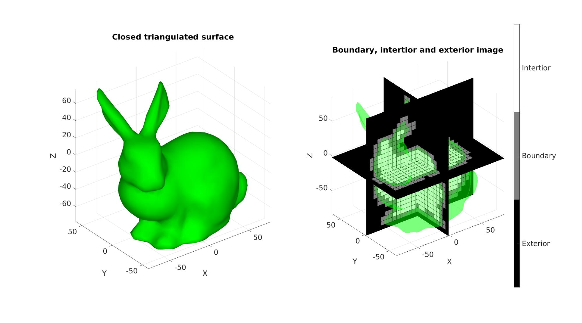
CONVERTING A TRIANGULATED SURFACE TO AN IMAGE WITH DESIRED SIZE, VOXEL SIZE AND ORIGIN
Defining an example triangulated surface model
[Fs,Vs]=stanford_bunny;
Setting control parameters
% Defining the full set of possible control parameters
voxelSize=6; % The output image voxel size.
imOrigin=min(Vs,[],1)-voxelSize;
imMax=max(Vs,[],1)+voxelSize;
imSiz=round((imMax-imOrigin)/voxelSize);
imSiz=imSiz([2 1 3]); %Image size (x, y corresponds to j,i in image coordinates, hence the permutation)

% Using |triSurf2Im| function to convert patch data to image data
[M,~]=triSurf2Im(Fs,Vs,voxelSize,imOrigin,imSiz);
Plotting the results
hf1=cFigure;
subplot(1,2,1);
title('Closed triangulated surface','FontSize',fontSize);
xlabel('X','FontSize',fontSize);ylabel('Y','FontSize',fontSize); zlabel('Z','FontSize',fontSize);
hold on;
gpatch(Fs,Vs,'g','none');
axis equal; view(3); axis tight;  grid on;  set(gca,'FontSize',fontSize);
camlight('headlight'); lighting phong;
set(gca,'fontSize',fontSize);

subplot(1,2,2);
title('Boundary, intertior and exterior image','FontSize',fontSize);
xlabel('X','FontSize',fontSize);ylabel('Y','FontSize',fontSize); zlabel('Z','FontSize',fontSize);
hold on;

gpatch(Fs,Vs,'g','none',faceAlpha2);

L_plot=false(size(M));
L_plot(:,:,round(size(M,3)/2))=1;
[Fm,Vm,Cm]=ind2patch(L_plot,double(M),'sk');
[Vm(:,1),Vm(:,2),Vm(:,3)]=im2cart(Vm(:,2),Vm(:,1),Vm(:,3),voxelSize*ones(1,3));
Vm=Vm+imOrigin(ones(size(Vm,1),1),:);
gpatch(Fm,Vm,Cm,'k');

L_plot=false(size(M));L_plot(round(size(M,1)/2),:,:)=1;
[Fm,Vm,Cm]=ind2patch(L_plot,M,'si');
[Vm(:,1),Vm(:,2),Vm(:,3)]=im2cart(Vm(:,2),Vm(:,1),Vm(:,3),voxelSize*ones(1,3));
Vm=Vm+imOrigin(ones(size(Vm,1),1),:);
gpatch(Fm,Vm,Cm,'k');

L_plot=false(size(M));L_plot(:,round(size(M,2)/2),:)=1;
[Fm,Vm,Cm]=ind2patch(L_plot,M,'sj');
[Vm(:,1),Vm(:,2),Vm(:,3)]=im2cart(Vm(:,2),Vm(:,1),Vm(:,3),voxelSize*ones(1,3));
Vm=Vm+imOrigin(ones(size(Vm,1),1),:);
gpatch(Fm,Vm,Cm,'k');

colormap(gray(3)); caxis([0 2]);
hc=colorbar;
set(hc,'YTick',[1/3 1 5/3]);
set(hc,'YTickLabel',{'Exterior','Boundary','Intertior'});
set(hc,'fontSize',fontSize);
axis equal; view(3); axis tight;  grid on;  set(gca,'FontSize',fontSize);
set(gca,'fontSize',fontSize);
drawnow;
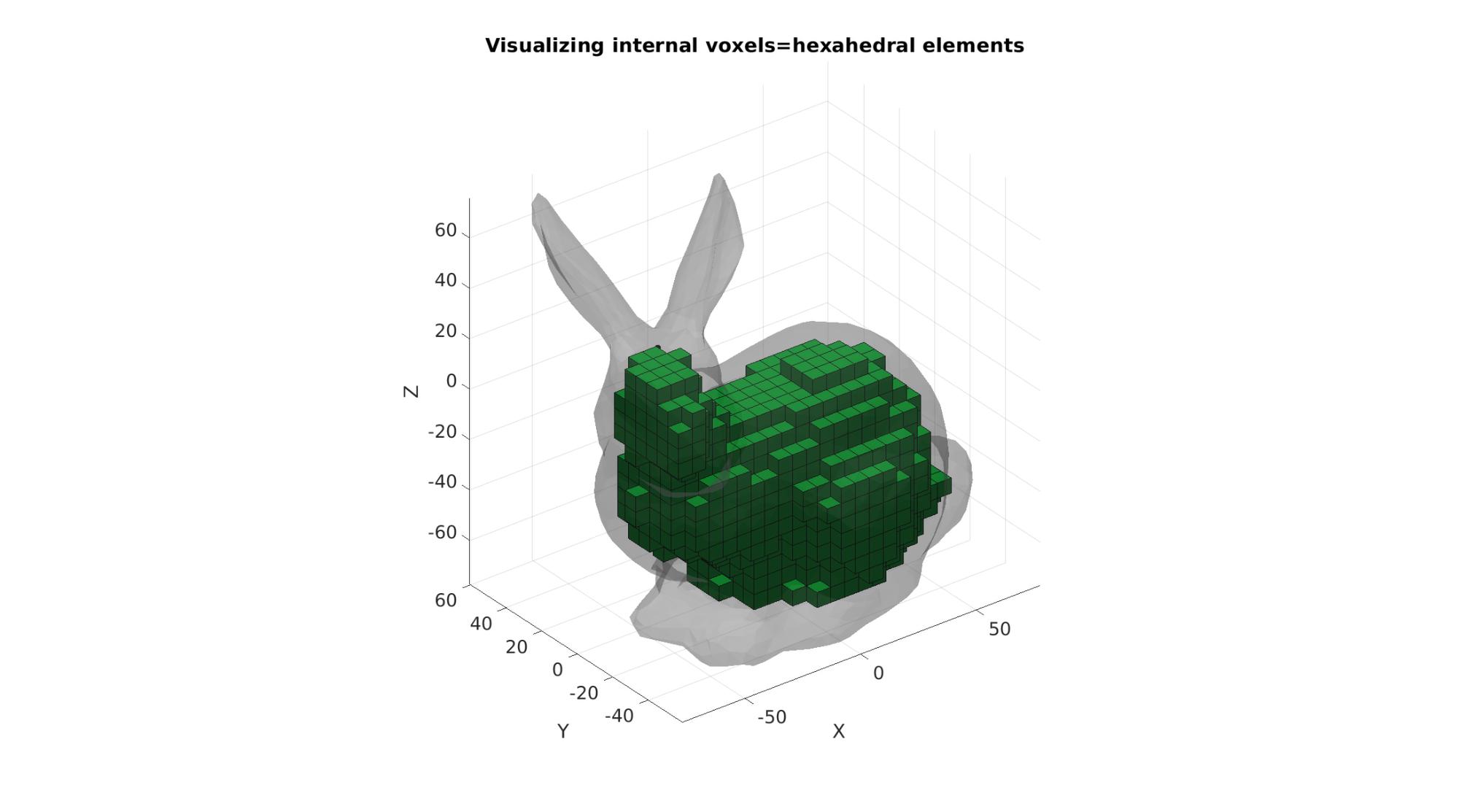
GET HEXAHEDRAL ELEMENT SET
L_model=(M==2); %Interior&Boundary choosen here

%Defining erosion/dilation kernel
k=3;
p=k-round(k./2);
hb=zeros(3,3);
hb(2,2,2)=1;
hb(2,2,1)=1;
hb(2,2,3)=1;
hb(1,2,2)=1;
hb(3,2,2)=1;
hb(2,3,2)=1;
hb(2,1,2)=1;

L_model_rep=zeros(size(L_model)+(2.*p));
L_model_rep(p+(1:size(L_model,1)),p+(1:size(L_model,2)),p+(1:size(L_model,3)))=L_model;
L_model_blur = convn(double(L_model_rep),hb,'valid');
L_model=L_model_blur>=(sum(hb(:)));

[E_hex,V_hex,C_hex]=ind2patch(L_model,M,'hu');

% Convert Coordinates
[V_hex(:,1),V_hex(:,2),V_hex(:,3)]=im2cart(V_hex(:,2),V_hex(:,1),V_hex(:,3),voxelSize*ones(1,3));
V_hex=V_hex+imOrigin(ones(size(V_hex,1),1),:);

% Use element2patch to get patch data to plot the model
[F_hex_cut1,C_hex_F]=element2patch(E_hex,C_hex);

%Pass through unique_patch to reduce "weight" of plot
[Fp,Vp,~,~,~,F_count]=unique_patch(F_hex_cut1,V_hex,[],5);
logicUni=F_count==1; %Logic for boundary faces

Fq=Fp(logicUni,:);
Vq=Vp;
[Fq,Vq,~]=patchCleanUnused(Fq,Vq);

[Ft,Vt]=quad2tri(Fq,Vq,'b');
Plotting the results
hf1=cFigure;
title('Visualizing internal voxels=hexahedral elements','FontSize',fontSize);
xlabel('X','FontSize',fontSize);ylabel('Y','FontSize',fontSize); zlabel('Z','FontSize',fontSize);
hold on;

gpatch(Fs,Vs,0.5*ones(1,3),'none',faceAlpha2);
gpatch(Fq,Vq,plotColors(2,:),'k');

camlight('headlight'); lighting flat;
axis equal; view(3); axis tight;  grid on;  set(gca,'FontSize',fontSize);
drawnow;

%Joining surface sets
F=[Fs;Ft+size(Vs,1)];
V=[Vs;Vt];
C_tet=[ones(size(Fs,1),1);2*ones(size(Ft,1),1)]; %Surface marker colors
Get hole point
[V_hole]=getInnerPoint(Ft,Vt,searchRadius,voxelSize/2,0);
plotV(V_hole,'r.','MarkerSize',25);

Get region point
L_in=(M==1);

[indInternal]=getInnerVoxel(double(L_in),searchRadius,0);

[I_in,J_in,K_in]=ind2sub(size(L_in),indInternal); %Convert to subscript coordinates
[X_in,Y_in,Z_in]=im2cart(I_in,J_in,K_in,voxelSize*ones(1,3));
V_in=[X_in Y_in Z_in];
V_in=V_in+imOrigin(ones(size(V_in,1),1),:);

plotV(V_in,'k.','MarkerSize',25);

DEFINE FACE BOUNDARY MARKERS
faceBoundaryMarker=C_tet;
Define region points
V_regions=[V_in];
Define hole points
V_holes=[V_hole];
Regional mesh parameters
[edgeLengths]=patchEdgeLengths(F,V);
edgeLengthsMean=mean(edgeLengths);
meanProposedVolume=edgeLengthsMean^3./(6*sqrt(2)); %For regular tetrahedron
regionA=meanProposedVolume;
CREATING THE SMESH STRUCTURE, meshing without the surface constraints imposed by the -Y this time.
stringOpt='-pq1.2AaY';

modelName='tetGenModel';

meshStruct.stringOpt=stringOpt;
meshStruct.Faces=F;
meshStruct.Nodes=V;
meshStruct.holePoints=V_holes;
meshStruct.faceBoundaryMarker=faceBoundaryMarker; %Face boundary markers
meshStruct.regionPoints=V_regions; %region points
meshStruct.regionA=regionA;
meshStruct.minRegionMarker=2; %Minimum region marker
meshStruct.modelName=modelName;
Mesh model using tetrahedral elements using tetGen (see: http://wias-berlin.de/software/tetgen/)
[meshOutput]=runTetGen(meshStruct); %Run tetGen
%%%%%%%%%%%%%%%%%%%%%%%%%%%%%%%%%%%%%%%%%%%%%
--- TETGEN Tetrahedral meshing --- 20-Apr-2023 10:34:25

%%%%%%%%%%%%%%%%%%%%%%%%%%%%%%%%%%%%%%%%%%%%%
--- Writing SMESH file --- 20-Apr-2023 10:34:25
----> Adding node field
----> Adding facet field
----> Adding holes specification
----> Adding region specification
--- Done --- 20-Apr-2023 10:34:25
--- Running TetGen to mesh input boundary--- 20-Apr-2023 10:34:25
Opening /mnt/data/MATLAB/GIBBON/data/temp/tetGenModel.smesh.
Delaunizing vertices...
Delaunay seconds:  0.033281
Creating surface mesh ...
Surface mesh seconds:  0.004077
Recovering boundaries...
Boundary recovery seconds:  0.062397
Removing exterior tetrahedra ...
Spreading region attributes.
Exterior tets removal seconds:  0.004416
Suppressing Steiner points ...
Steiner suppression seconds:  8e-06
Recovering Delaunayness...
Delaunay recovery seconds:  0.012048
Refining mesh...
  3644 insertions, added 757 points, 9402 tetrahedra in queue.
  1213 insertions, added 63 points, 596 tetrahedra in queue.
  1617 insertions, added 101 points, 2523 tetrahedra in queue.
Refinement seconds:  0.056307
Smoothing vertices...
Mesh smoothing seconds:  0.065863
Improving mesh...
Mesh improvement seconds:  0.003643
Jettisoning redundant points.

Writing /mnt/data/MATLAB/GIBBON/data/temp/tetGenModel.1.node.
Writing /mnt/data/MATLAB/GIBBON/data/temp/tetGenModel.1.ele.
Writing /mnt/data/MATLAB/GIBBON/data/temp/tetGenModel.1.face.
Writing /mnt/data/MATLAB/GIBBON/data/temp/tetGenModel.1.edge.

Output seconds:  0.0384
Total running seconds:  0.280716

Statistics:

  Input points: 2729
  Input facets: 5460
  Input segments: 8185
  Input holes: 1
  Input regions: 1

  Mesh points: 3706
  Mesh tetrahedra: 14930
  Mesh faces: 32590
  Mesh faces on exterior boundary: 5460
  Mesh faces on input facets: 5460
  Mesh edges on input segments: 8185
  Steiner points inside domain: 977

--- Done --- 20-Apr-2023 10:34:26

%%%%%%%%%%%%%%%%%%%%%%%%%%%%%%%%%%%%%%%%%%%%%
--- Importing TetGen files --- 20-Apr-2023 10:34:26
--- Done --- 20-Apr-2023 10:34:26
Access model element and patch data
F_tet_cut1=meshOutput.faces;
V_tet=meshOutput.nodes;
C_tet=meshOutput.faceMaterialID;
E_tet=meshOutput.elements;

indBoundary=meshOutput.facesBoundary(meshOutput.boundaryMarker==1,:);
indBoundary=unique(indBoundary(:));
MERGING NODE SETS
V=[V_tet;V_hex];
E_hex=E_hex+size(V_tet,1);

[~,V,ind1,ind2]=mergeVertices(F_tet_cut1,V);

E_tet=ind2(E_tet);
E_hex=ind2(E_hex);
indBoundary=ind2(indBoundary);

E={E_tet, E_hex};
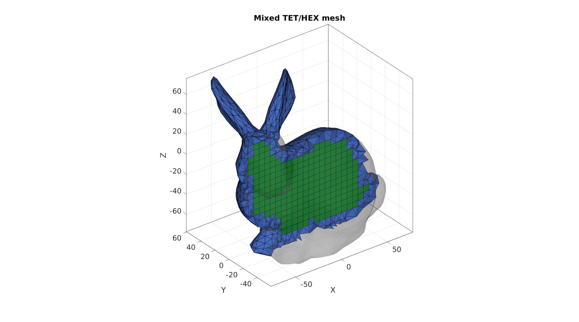
Visualizing mesh
cFigure;
title('Mixed TET/HEX mesh','FontSize',fontSize);

%Selecting half of the model to see interior
X=V(:,2); XE=mean(X(E{1}),2);
L=XE>mean(X);
[F_tet_cut1,~]=element2patch(E{1}(L,:),C_tet(L));

%Selecting half of the model to see interior
X=V(:,2); XE=mean(X(E{2}),2);
L=XE>mean(X);
[F_hex_cut1,~]=element2patch(E{2}(L,:),C_hex(L));

gpatch(F_tet_cut1,V,plotColors(1,:),'k');
gpatch(F_hex_cut1,V,plotColors(2,:),'k');
gpatch(Fs,Vs,0.5*ones(1,3),'none',faceAlpha2);

axisGeom(gca,fontSize);
camlight headlight;
set(gca,'FontSize',fontSize);
drawnow;
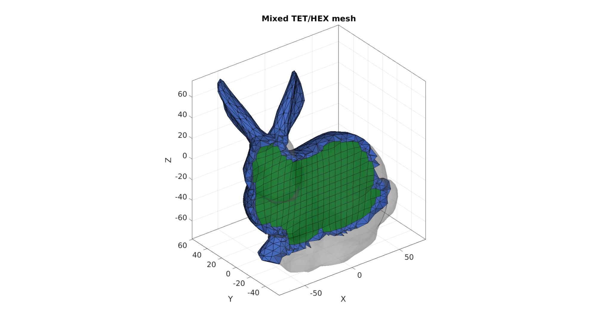
Smoothing meshes
cPar.Method='LAP';
cPar.n=25;
cPar.RigidConstraints=indBoundary;

[F1,~]=element2patch(E{1},[]);
[F1,~,~]=uniqueIntegerRow(F1);
[F2,~]=element2patch(E{2},[]);
[F2,~,~]=uniqueIntegerRow(F2);
[~,IND_V1,~]=tesIND(F1,V,0);
[~,IND_V2,~]=tesIND(F2,V,0);
IND_V=[IND_V1 IND_V2];

[VS]=tesSmooth([],V,IND_V,cPar);
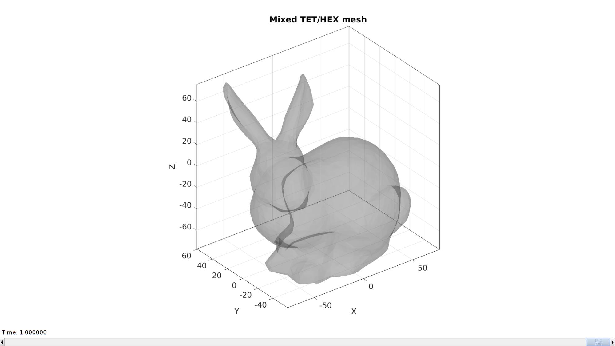
Visualizing mesh
hf=cFigure;
title('Mixed TET/HEX mesh','FontSize',fontSize);

%Selecting half of the model to see interior
X=V(:,2); XE=mean(X(E{1}),2);
L=XE>mean(X);
[F_tet_cut1,~]=element2patch(E{1}(L,:),C_tet(L));

%Selecting half of the model to see interior
X=V(:,2); XE=mean(X(E{2}),2);
L=XE>mean(X);
[F_hex_cut1,~]=element2patch(E{2}(L,:),C_hex(L));

hp1=gpatch(F_tet_cut1,VS,plotColors(1,:),'k');
hp2=gpatch(F_hex_cut1,VS,plotColors(2,:),'k');
gpatch(Fs,Vs,0.5*ones(1,3),'none',faceAlpha2);

axisGeom(gca,fontSize);
camlight headlight;
set(gca,'FontSize',fontSize);
drawnow;

Set up animation
nSteps=25; %Number of animation steps
X=V(:,2);
XE1=mean(X(E{1}),2);
XE2=mean(X(E{2}),2);

animStruct.Time=linspace(0,1,nSteps); %Time vector
cutLevel=linspace(min(X(:)),max(X(:)),nSteps); %Property to set

for q=1:1:nSteps %Step through time
    cutLevelNow=cutLevel(q); %The current cut level

    L1=XE1>cutLevelNow;
    [F_tet_cut1,~]=element2patch(E{1}(L1,:));

    L2=XE2>cutLevelNow;
    [F_hex_cut1,~]=element2patch(E{2}(L2,:));

    %Set entries in animation structure
    animStruct.Handles{q}=[hp1 hp2]; %Handles of objects to animate
    animStruct.Props{q}={'Faces','Faces'}; %Properties of objects to animate
    animStruct.Set{q}={F_tet_cut1,F_hex_cut1}; %Property values for to set in order to animate
end

%Add animation layer
anim8(hf,animStruct);

GIBBON
Kevin M. Moerman ([email protected])
GIBBON footer text
License: https://github.com/gibbonCode/GIBBON/blob/master/LICENSE
GIBBON: The Geometry and Image-based Bioengineering add-On. A toolbox for image segmentation, image-based modeling, meshing, and finite element analysis.
Copyright (C) 2006-2022 Kevin Mattheus Moerman and the GIBBON contributors
This program is free software: you can redistribute it and/or modify it under the terms of the GNU General Public License as published by the Free Software Foundation, either version 3 of the License, or (at your option) any later version.
This program is distributed in the hope that it will be useful, but WITHOUT ANY WARRANTY; without even the implied warranty of MERCHANTABILITY or FITNESS FOR A PARTICULAR PURPOSE. See the GNU General Public License for more details.
You should have received a copy of the GNU General Public License along with this program. If not, see http://www.gnu.org/licenses/.